 Sign-up for free online course on ANSYS simulations!
Problem Specification
1. Start-up and preliminary set-up
2. Specify element type and constants
3. Specify material properties
4. Specify geometry
5. Mesh geometry
6. Specify boundary conditions
7. Solve!
8. Postprocess the results
9. Validate the results
Step 5: Mesh geometry
Bring up the MeshTool:
Main Menu > Preprocessor > MeshTool
The MeshTool is used to control and generate the mesh.
Set Meshing Parameters
The element type and material property set to be used in meshing are automatically selected since we have only one of each. To check this using the MeshTool, make sure Global is selected under Element Attributes and click on Set. You will see that the correct element type and material number are already selected in the Meshing Attributes menu. There is no real constant set required for the SOLID45 element with default options (which we haven't changed). Click Cancel.
Set Mesh Size
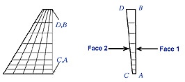
Two views of the FE mesh we want to use are shown in the figure below.
...
Pick line L5 in the Graphics window and click OK in the pick menu. Enter 8 for No. of element divisions, 1/0.3 for Spacing Ratio and click OK.
Mesh Volume
We'll mesh the volume using hexahedral elements (rather than tetrahedral elements). So choose Hex under Shape in the MeshTool.
...