 Sign-up for free online course on ANSYS simulations!
...
Utility Menu > Plot > Lines
Under Size Controls and Lines, click Set. This brings up a pick menu.
...
Pick lines L7,L9, and L11 in the Graphics window and click OK in the pick menu. Enter 16 for No. of element divisions, 0.3 for Spacing Ratio and click Apply.
Pick line L5 in the Graphics window and click OK in the pick menu. Enter 16 for No. of element divisions, 1/0.3 for for Spacing Ratio and click OK.
Select Volumes for Mesh: and Hex for Shapes:, then click Mesh.
Since we applied the BCs to the finite-element model rather than the solid geometry model, the BCs were deleted along with the mesh. So we have to reapply the BCs again. Repeat step6 to reapply the BCs. It might feel like a chore but consider it as good practice. Since the vface2 table for applying the BC on face 2 already exists, you need not recreate the function or the table.
...
Main Menu > General Postproc > Plot results > Contour Plot > Nodal Solu
Select Stress from the left list, Y-direction SY from the right list and click OK.
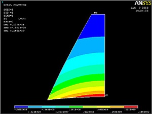
(Click Picture for Larger Image)
...
Utility Menu > File > Exit
Select Save Everything and click OK.
Reference
Cook, R.D., Malkus, D.S., Plesha, M.E., and Witt, R.J., Concepts and Applications of Finite Element Analysis, Fourth Edition, John Wiley and Sons, Inc., 2002.
Back to Problem Specification