 Sign-up for free online course on ANSYS simulations!
...
The meshed face should look as follows:
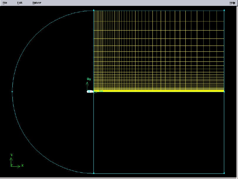
(Click picture for larger image)
...
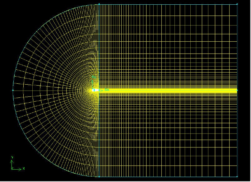
The resultant mesh should be symmetric about CG as shown in the figure below.
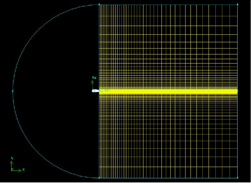
(Click picture for larger image)
...
Next, we will split the top and bottom edges of the airfoil into two edges so that we have better control of the mesh point distribution. Figure of the splitting edges is shown below.
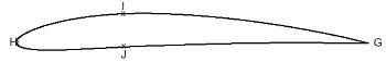
We need to do this because a non-uniform grid spacing will be used for x<0.3c and a uniform grid spacing for x>0.3c. To split the top edge into HI and IG, select
...
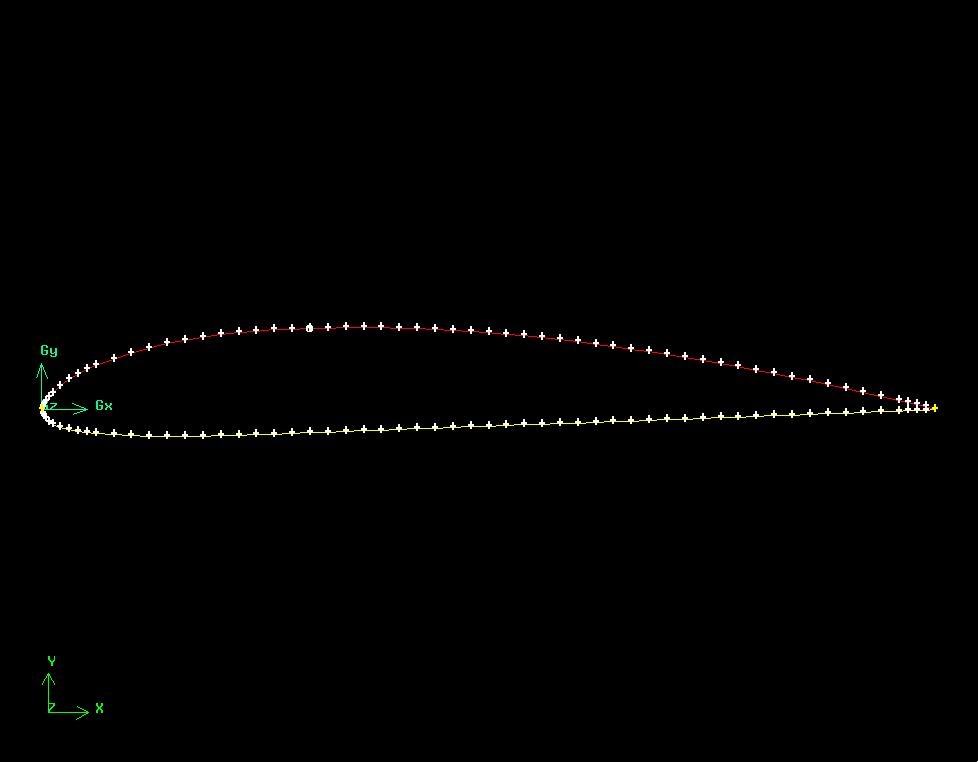
Select the top edge of the airfoil by Shift-clicking on it. You should see something similar to the picture below:
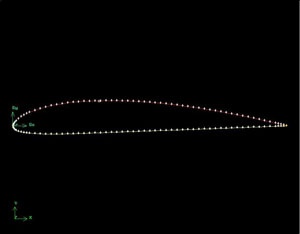
(Click picture for larger image)
...
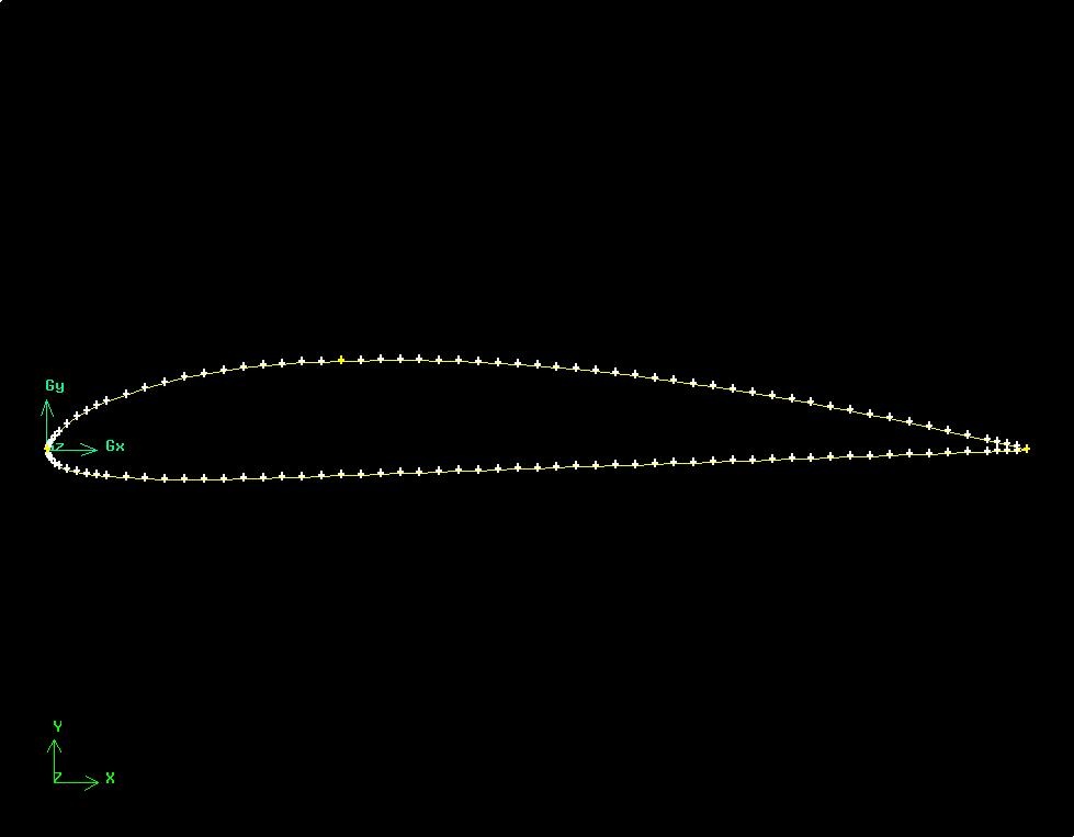
You should see that the white circle has moved to the correct location on the edge.
(Click picture for larger image)
Click Apply. You will see a message saying ``Edge edge.1 was split, and edge edge.3 created'' in the Transcript window.
(Click picture for larger image)
...
Mesh the face. The resultant mesh is shown below.
(Click picture for larger image)
...