 Sign-up for free online course on ANSYS simulations!
Step 7: Validate the Results
Report Force
| Info | |||||||||
|---|---|---|---|---|---|---|---|---|---|
| |||||||||
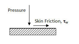
| Wiki Markup | FLUENT report forces in term of pressure force and viscous force. For instance, we are interested in the drag on the airfoil, (Drag) ~total~total = (Drag) ~pressure~pressure + (Drag)viscous
Drag due to pressure:
Drag due to viscous effect:
where ed is the unit vector parallel to the flow direction. n is unit vector perpendicular to the surface of airfoil. t is unit vector parallel to the surface of airfoil. Similarly, if we are interested in the lift on the airfoil, (Lift) = (Lift)pressure + (Lift)viscous Lift due to pressure:
Lift due to viscous effect:
where el is the unit vector perpendicular to the flow direction. n is unit vector perpendicular to the surface of airfoil. t is unit vector parallel to the surface of airfoil. |
Report Force
We will first investigate the Drag on the airfoil.
Main Menu > Report > Forces...
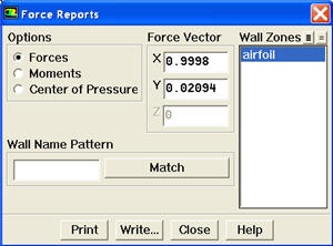
Select Forces. Under Force Vector, enter 0.9998 next to X. Enter 0.02094 next to Y. Select airfoil under Wall Zones. Click Print.
Here's is what we see in the main menu:
| No Format |
|---|
Force vector: (0.99980003 0.02094 0) pressure viscous total pressure viscous total zone name force force force coefficient coefficient coefficient n n n ------------------------- -------------- -------------- -------------- -------------- -------------- -------------- airfoil 3.8125084 0 3.8125084 0.0024897052 0 0.0024897052 ------------------------- -------------- -------------- -------------- -------------- -------------- -------------- net 3.8125084 0 3.8125084 0.0024897052 0 0.0024897052 |
...
Cd = (Cd)pressure + (Cd)skin friction
...
| Info | ||
|---|---|---|
| ||
In reality, (Cd)skin friction has biggest contribution to drag but ignored because of the inviscid model that we specify. (Cd)pressure should be zero, but it is not zero because of inaccuracies and numerical dissipation during the computation. |
Now, let's look at the lift coefficient.
Main Menu > Report > Forces...
Select Forces. Under Force Vector, enter -0.02094 next to X. Enter 0.9998 next to Y. Select airfoil under Wall Zones. Click Print.
Here's is what we see in the main menu:
...
Following table shows comparison of modeling result with experimental data.
...
Cl
...
Cd
...
FLUENT
...
.
...
0.00249
...
Experiment
...
0.6
...
0.007
...
% Dif
...
7.8%
...
Cl | Cd | |
|---|---|---|
FLUENT Fine Mesh | 0.649 | 0.00137 |
Experiment | 0.6 | 0.007 |
Theory | - | 0 |
...