 Sign-up for free online course on ANSYS simulations!
Step 2: Mesh Geometry in GAMBIT
Mesh Faces
We'll mesh each of the 3 faces separately to get our final mesh. Before we mesh a face, we need to define the point distribution for each of the edges that form the face i.e. we first have to mesh the edges. We'll select the mesh stretching parameters and number of divisions for each edge based on three criteria:
...
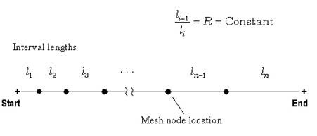
The edge mesh parameters we'll use for controlling the stretching are successive ratio, first length and last length. Each edge has a direction as indicated by the arrow in the graphics window. The successive ratio Ris the ratio of the length of any two successive divisions in the arrow direction as shown below. Go to the index of the GAMBIT User Guide and look under Edge>Meshing for this figure and accompanying explanation. This help page also explains what the first and last lengths are; make sure you understand what they are.
Operation Toolpad > Mesh Command Button  > Edge Command Button
  > Mesh Edges
Select the edge GA. The edge will change color and an arrow and several circles will appear on the edge. This indicates that you are ready to mesh this edge. Make sure the arrow is pointing upwards. You can reverse the direction of the edge by clicking on the Reverse button in the Mesh Edges menu. Enter a ratio of 1.15. This means that each successive mesh division will be 1.15 times bigger in the direction of the arrow. Select Interval Count under Spacing. Enter 45 for Interval Count. Click Apply. GAMBIT will create 45 intervals on this edge with a successive ratio of 1.15.
...
Operation Toolpad > Mesh Command Button > Face Command Button  > Mesh Faces
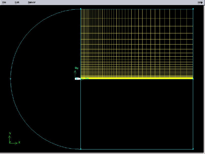
Select the face rect1. The face will change color. You can use the defaults of Quad (i.e. quadrilaterals) and Map. Click Apply.
The meshed face should look as follows:
...
| newwindow | ||||
|---|---|---|---|---|
| ||||
https://confluence.cornell.edu/download/attachments/90744014/02face1full.jpg?version=2 |
Next mesh face rect2 in a similar fashion. The following table shows the parameters to use for the different edges:
Edges | Arrow Direction | Successive Ratio Ratio | Interval Count |
|---|---|---|---|
EG and CD | Downwards | 1.15 | 45 |
...
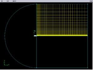
The resultant mesh should be symmetric about CG as shown in the figure below.
...

| newwindow | ||||
|---|---|---|---|---|
| ||||
https://confluence.cornell.edu/download/attachments/90744014/02face2full.jpg?version=2 |
Split Edges
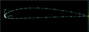
Next, we will split the top and bottom edges of the airfoil into two edges so that we have better control of the mesh point distribution. Figure of the splitting edges is shown below.
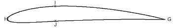
We need to do this because a non-uniform grid spacing will be used for x<0.3c and a uniform grid spacing for x>0.3c. To split the top edge into HI and IG, select
...
Select the top edge of the airfoil by Shift-clicking on it. You should see something similar to the picture below:
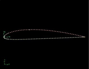
(Click picture for larger image)
We'll use the point at x=0.3c on the upper surface to split this edge into HI and IG. To do this, enter 0.3 for x: under Global. If your c is not equal to one, enter the value of 0.3*c instead of just 0.3.For instance, if c=4, enter 1.2. From here on, whenever you're asked to enter (some factor)*c, calculate the appropriate value for your c and enter it.You should see that the white circle has moved to the correct location on the edge.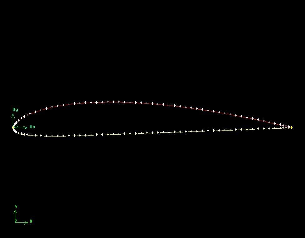
( Click picture for larger image)Click Apply. You will see a message saying ``Edge "Edge edge.1 was split, and edge edge.3 created'' in the Transcript window.
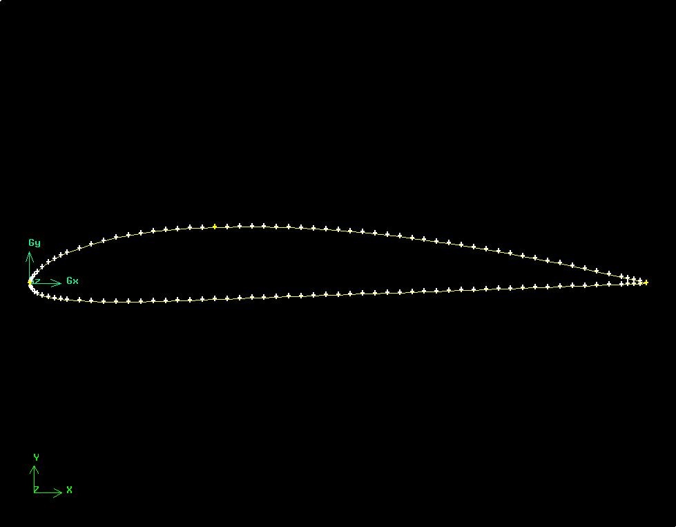
(Click picture for larger image)
Note the yellow marker in place of the white circle, indicating the original edge has been split into two edges with the yellow marker as its dividing point.
Repeat this procedure for the lower surface to split it into HJ and JG. Use the point at x=0.3c on the lower surface to split this edge.
| newwindow | ||||
|---|---|---|---|---|
| ||||
https://confluence.cornell.edu/download/attachments/90744014/airfoil_split_sm.jpg |
Finally, let's mesh the face consisting of circ1 and the airfoil surface. For edges HI and HJ on the front part of the airfoil surface, use the following parameters to create edge meshes:
...
Operation Toolpad > Mesh Command Button > Edge Command Button  >Summarize Edge Mesh
Select edge IG and then Elements under Component and click Apply. This will give the total number of nodes (i.e. points) and elements (i.e. divisions) on the edge in the Transcriptwindow. The number of divisions on edge IG is 3635. (If you are using a different geometry, this number will be different; I'll refer to it as NIG). So the Interval Count for edge AF is NHI+NIG= 40+3635= 76 75.
Similarly, determine the number of divisions on edge JG. This comes out as 35 for the current geometry. So the Interval Count for edge EF is 75.
Create the mesh for edges AF and EF with the following parameters:
...
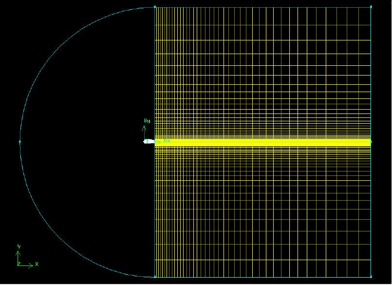
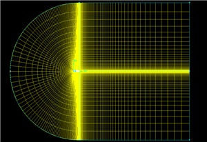
Mesh the face. The resultant mesh is shown below. 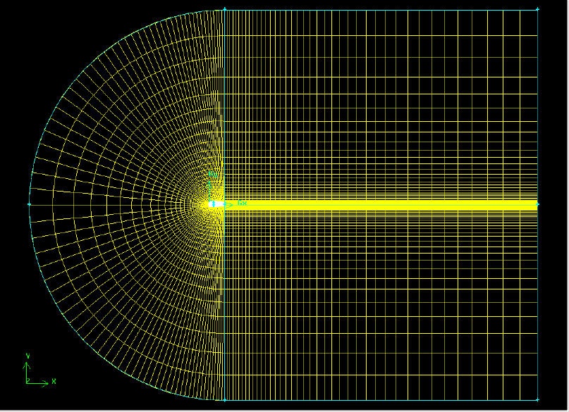
(Click picture for larger image)
| newwindow | ||||
|---|---|---|---|---|
| ||||
https://confluence.cornell.edu/download/attachments/90744014/airfoil%20mesh.jpg |
Go to Step 3: Specify Boundary Types in GAMBIT