 Sign-up for free online course on ANSYS simulations!
Problem Specification
1. Create Geometry in GAMBIT
2. Mesh Geometry in GAMBIT
3. Specify Boundary Types in GAMBIT
4. Set Up Problem in FLUENT
5. Solve!
6. Analyze Results
7. Refine Mesh
Problem 1
Problem 2
Step 1: Create Geometry in GAMBIT
If you wish to skip the steps for grid creation, you can download the mesh file here (right-click and select Save As...) and go to Step 4. |
This tutorial leads you through the steps for generating a mesh in GAMBIT for an airfoil geometry. This mesh can then be read into FLUENT for fluid flow simulation.
...
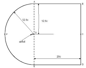
The farfield boundary we'll use is the line ABCDEFA in the figure above. c is the chord length.
Start GAMBIT
Create a new directory called airfoil and start GAMBIT from that directory by typing gambit -id airfoil at the command prompt.
Under Main Menu, select Solver > FLUENT 5/6 since the mesh to be created is to be used in FLUENT 6.0.
Import Edge
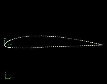
To specify the airfoil geometry, we'll import a file containing a list of vertices along the surface and have GAMBIT join these vertices to create two edges, corresponding to the upper and lower surfaces of the airfoil. We'll then split these edges into 4 distinct edges to help us control the mesh size at the surface.
The file containing the vertices for the airfoil can be downloaded here: naca4412.dat (right click and select Save As...)
Let's take a look at the naca4412.dat file:

The first line of the file represents the number of points on each edge (61) and the number of edges (2). The first 61 set of vertices are connected to form the edge corresponding to the upper surface; the next 61 are connected to form the edge for the lower surface.
...
Note: NACA series geometry can be found in many online website. One such website is:
http://www.pagendarm.de/trapp/programming/java/profiles/NACA4.html![]()
Main Menu > File > Import > ICEM Input ...
For File Name, browse and select the naca4412.dat file. Select both Vertices and Edges under Geometry to Create: since these are the geometric entities we need to create. Deselect Face. Click Accept.
(Click picture for larger image)
...