 Sign-up for free online course on ANSYS simulations!
| Panel |
|---|
Problem Specification |
...
If you wish to skip the steps for grid creation, you can download the mesh file here (right-click and select Save As...) and go to Step 4. |
| newwindow | ||||
|---|---|---|---|---|
| ||||
https://confluence.cornell.edu/download/attachments/90742023/01farfield_boundary.jpg?version=1 |
...
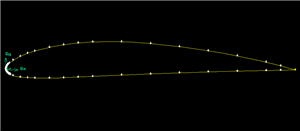
The file containing the vertices for the airfoil can be downloaded here: naca4412.dat (right click and select Save As...)
Let's take a look at the naca4412.dat file:
...
Main Menu > File > Import > ICEM Input ...
For File Name, browse and select the naca4412.dat file. Select both Vertices and Edges under Geometry to Create: since these are the geometric entities we need to create. Deselect Face. Click Accept.
| newwindow | ||||
|---|---|---|---|---|
| ||||
https://confluence.cornell.edu/download/attachments/90742023/NACA4412.jpg |
| Info | ||
|---|---|---|
| ||
We have more points around the nose area because of the high curvature around the nose. |
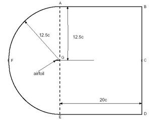
Create Farfield Boundary
Next, we will create the following farfield boundary. This picture of the
...
Create the following vertices by entering the coordinates under Global and the label under Label:
Label | x | y | z |
A | c | 12.5c | 0 |
B | 21c | 12.5c | 0 |
C | 21c | 0 | 0 |
D | 21c | -12.5c | 0 |
E | c | -12.5c | 0 |
F | -11.5 | 0 | 0 |
G | c | 0 | 0 |
...
Create the edge AB by selecting the vertex A followed by vertex B. Enter AB for Label. Click Apply. GAMBIT will create the edge. You will see a message saying something like "Created edge: AB'' in the Transcript window.
...
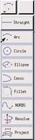
Next we'll create the circular arc AF. Right-click on the Create Edge button and select Arc.
In the Create Real Circular Arc menu, the box next to Center will be yellow. That means that the vertex you select will be taken as the center of the arc. Select vertex G and click Apply. Now the box next to End Points will be highlighted in yellow. This means that you can now select the two vertices that form the end points of the arc. Select vertex A and then vertex F. Enter AF under Label. Click Apply.
If you did this right, the arc AF will be created. If you look in the transcript window, you'll see a message saying that an edge has been created.
...
To create the face rect1, select the edges AB, BC, CG, and GA. Enter rect1for the label and click Apply. GAMBIT will tell you that it has "Created face: rect1'' in the transcript window.
...
right click on the Boolean Operations Button  and select Subtract
The Face box will be highlighted yellow. Shift click to select circ1, the outer semi-circular boundary. Then select the lower box labeled Subtract Faces which will allow you to select faces to subtract from our outer boundary. Select the airfoil face and click apply.
...