 Sign-up for free online course on ANSYS simulations!
...
Operation Toolpad > Geometry Command Button ![]() *> Vertex Command Button*
*> Vertex Command Button* ![]() *> Create Vertex *
*> Create Vertex * 
Create the vertices by entering the coordinates under Global and the label under Label:
Click the FIT TO WINDOW button to scale the display so that you can see all the vertices. The resulting image should look like this:

(Click picture for larger image)
...
Operation Toolpad > Geometry Command Button  *> Edge Command Button *
  *> Create Edge*
 ![]()
Create the edge AB by selecting the vertex A followed by vertex B. Enter AB for Label. Click Apply. GAMBIT will create the edge. You will see a message saying something like "Created edge: AB'' in the Transcript window.
Similarly, create the edges BC, CD, DE, EF, FA and CF. Click on the ![]() to select the vertices from the list and move them to the picked list. You can also hold the shift button and mouse click the vertices for selection.The resulting image should look like this.
to select the vertices from the list and move them to the picked list. You can also hold the shift button and mouse click the vertices for selection.The resulting image should look like this.
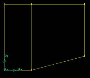
(Click picture for larger image)
...
Operation Toolpad > Geometry Command Button ![]() *> Face Command Button*
*> Face Command Button*  *> Form Face*
This brings up the Create Face From Wireframe menu. Recall that we had selected vertices in order to create edges. Similarly, we will select edges in order to form a face.
...