 Sign-up for free online course on ANSYS simulations!
...
Main Menu > Preprocessor > Meshing > Mesh Tool
Select Clear under Mesh and Pick All in the pick menu. The mesh is deleted.
...
This brings up the Delete Elements pick menu. Select Pick All.
Main Menu > Preprocessor > Modeling > Delete > Nodes
This brings up the Delete Nodes pick menu. Select Pick All.
We will now re-mesh the geometry.
In the MeshTool menu, make sure Global is selected under Element Attributes and click on Set. Select 1 SOLID92 for Element type number. Then, make sure the overall element size level is set to 1 under SmartSize. Also, make sure Volumes is selected in the drop-down list next to Mesh and the default options of Tet and Free meshing are selected under Shape. Click on the Mesh button and click on Pick All.
In the MeshTool, select KeyPoints in the drop-down list next to Refine at:. Click on the Refine button. This brings up the Refine mesh at Keypoints pick menu. Enter 1 under List of items and hit Enter (keyboard). Then, enter 5 and click OK. Recall that keypoints 1 and 5 are located at the point of contact. Keypoint 1 belongs to the lower disk and keypoint 5 to the upper disk. We selected both keypoints as we want to refine the mesh on the upper and lower disks.
This brings up the Refine Mesh at keypoint menu. This menu allows us to select the level of refinement we want to achieve. We'll use the minimal option of 1(Minimal), which is the default. Click OK. 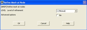
The mesh is now refined around the selected nodes.
...
List the principal stresses: Main Menu > General Postproc > List Results > Nodal Solution
Select Stress from the left list, Principals SPRIN from the right and click OK.
Scroll all the way down in this window. You will find that the new maximum principal stress is -1694.5N/mm2.
List the principal maximum displacements: Main Menu > General Postproc > List Results > Nodal Solution
Select DOF solution from the left list, Translation UY from the right and click OK.
You will find that the new displacement for nodes attached to the upper area of the upper disk is again the same and has a value of -0.25800E-01 =0.0258 mm.
...
Utility Menu > File > Exit
Select Save Everything and click OK.
Reference
Boresi, A.P., and Schmidt, R.J., Advanced Mechanics of Materials, Sixth Edition, John Wiley and Sons, Inc., 2003.