 Sign-up for free online course on ANSYS simulations!
Problem Specification
1. Start-up and preliminary set-up
2. Specify element type and constants
3. Specify material properties
4. Specify geometry
5. Mesh geometry
6. Specify boundary conditions
7. Solve
8. Postprocess the results
9. Validate the results
Step 5: Mesh geometry
We'll start by meshing the upper and lower disks using SOLID92 elements . Then, we'll mesh the target and contact surfaces using TARGE170 elements and CONT175 elements respectively.
...
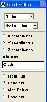
In the Select Entities menu, make sure Nodes is selected in the pull-down menu at the top and select By Location below that. Select Y coordinates below that and enter -2,0.5 as the Min,Max. Then select Reselect below that since we want to select a subset of the already selected nodes. Click OK.
...
In the Select Entities menu, make sure Nodes is selected in the pull-down menu at the top and select By Location below that. Select Y coordinates below that and enter -0.5,1.5 as the Min,Max. Then select Reselect below that since we want to select a subset of the already selected nodes. Click OK.
...
Save Your Work
Toolbar > SAVE_DB