 Sign-up for free online course on ANSYS simulations!
...
- Turn on node numbers (in addition to keypoint and area numbers) using Utility Menu > PlotCtrls > Numbering
- Display elements and nodes together: Utility Menu > PlotCtrls > Multi-Plot Ctrls > OK. Leave only Nodes and Elements turned on and click OK. Select Utility Menu > Plot > Multi-Plots.
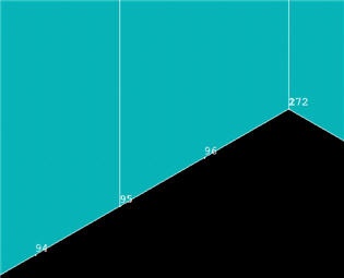
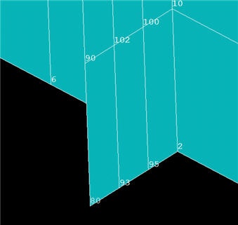
- Zoom into the bottom-center of the model as in the snaphsot below. At the bottom of the symmetry plane, you should notice that there are actually two nodes, 2 and 172. Node 2 is associated with the original area and node 172 with the copy. We'll merge coincident nodes a little later. (Note that your node numbers may be different from mine since numbering can vary on different computer systems.)
...
* h4. Copy Mesh in y-Direction
Plot areas: Utility Menu > Plot > Areas
Click on the Fit View and Isometric View icons in the rightmost part of the GUI.
Copy areas: Main Menu > Preprocessor > Modeling > Copy > Areas
Pick A1, A2, and A5 and click OK.
Copy Areas menu: Leave Number of copies as 2. For Y-offset, enter L1/(2*NSY); delete X-offset; leave Z-offset blank and click OK.
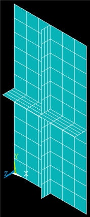
Check the resulting mesh for sub-section ABCD: Utility Menu > Plot > Elements
Turn-off node numbers to reduce clutter.
Copy Sub-Section ABCD
How many copies of sub-sectionABCD do we need to make in the x- and y-directions? What are the values of X-Offset and Y-Offset in each case? Jot your answers down so that you can check the values below.
Copy areas: Main Menu > Preprocessor > Modeling > Copy > Areas > Pick All
Copy Areas menu: Number of copies = NSX; X-offset = W1/NSX; Y- and Z-offsets should be blank or zero. Click Apply.
Repeat copy in y-direction: Select Pick All again in the pick menu.
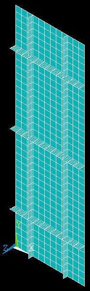
Copy Areas menu: Number of copies = NSY; Y-offset = L1/NSY; X- and Z-offsets should be blank or zero. Click OK.
Check the resulting mesh: Utility Menu > Plot > Elements
Merge Coincident Entities
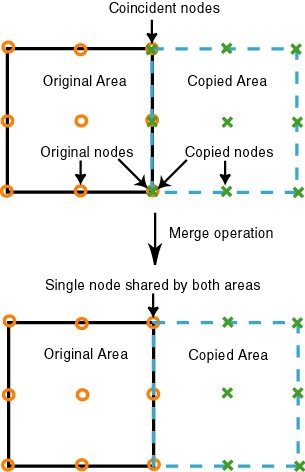
We saw earlier that the copy operations resulted in coincident nodes, keypoints, etc. along shared boundaries. We need to merge these coincident items so that separate portions of the model are combined into one. Otherwise, the various portions will live as independent entities and loads applied to one portion will not be transferred to its neighbors. The effect of the merge operation is shown schematically below.
View documentation about the merge utility: ANSYS Help > Contents > Modeling and Meshing Guide > Number Control and Element Reordering > Number Control
This section has useful information about merging entities. It indicates that one can either merge keypoints, nodes, etc. individually or merge allcoincident entities at once (with ANSYS ensuring that they are merged in the proper sequence). Since we'd like to palm off as much work as possible to ANSYS, we'll use the latter option.
Select Main Menu> Preprocessor> Numbering Ctrls> Merge Items
For Type of item to be merged, select All and click OK. This will merge all coincident entities.
Earlier we saw that nodes 2 and 172 were coincident. Zoom in on this region again with node numbers turned on. What do you see?
If you performed the merge operation correctly, you'll see that the higher numbered node has been deleted and the two coincident nodes have been replaced by a single node.
Save: Toolbar > SAVE_DB
...