 Sign-up for free online course on ANSYS simulations!
Step 8: Postprocess the results
Enter Postprocessing module to analyze
...
solution
Main Menu > General Postproc
Select Results Summary.
This shows you the cyclic frequencies of the ten modes. Compare with the values in the book.
...
Read Results > By Set Numbers
Enter 2 for NSET.
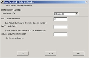
Click OK.
Plot Results > Deformed Shape
Select Def+undeformed.
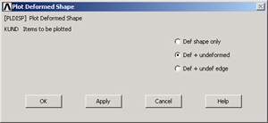
Click OK.
This plots the mode shape for mode 2. Similarly, look at the other mode shape and compare them with figure 11.17-2 in the book.
Find Mode Numbers
Table 11.17-1 gives amplitude values for selected d.o.f. for three nodes.
...
Utility Menu > PlotCtrls > Numbering
Turn on Node Numbers.
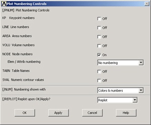
Click OK.
If you need to refresh the screen: Utility Menu > Plot > Multi-plots
...
Node Numbers |
| Cook et al. | ANSYS |
16 | 17 | ||
41 | 42 | ||
51 | 32 |
|
Determine the Displacement Amplitude
To determine the displacement amplitude at node 17 for mode 3,
General Post Proc > Read Results > By Set Number
Enter 3 for NSET.
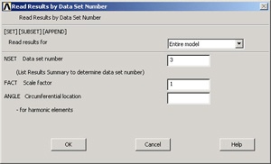
General Post Proc > List Results > Nodal Solution
Select UCOMP.
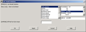
From the list, the displacement amplitude, denoted as USUM, is 23.9e-3. The corresponding value in table 11.17-1 is 23.8e-3. Similarly, you can determine the other entries in the table. Note that the rotational d.o.f. to use for the second row in the table is ROTZ_._
Save your work
Click on SAVE_DB in the ANSYS Toolbar to save the database.