 Sign-up for free online course on ANSYS simulations!
| Panel |
|---|
Author: Rajesh Bhaskaran, Cornell University Problem Specification |
Problem Specification
The problem considered here is the curved beam of uniform trapezoidal cross-section in example 6.15 of of Cook et al. The beam is bent in its own plane by moments M. The problem is not axisymmetric because displacements have circumferential as well as radial and axial components. So we use 3D solid elements rather than axisymmetric elements. The geometry can nevertheless be described in cylindrical coordinates.
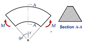
We would like to obtain the stresses for the trapezoidal cross-section AA shown above. Stresses in the curved beam do not vary with θ, so we can reduce the model and analyze only a typical slice between two closely spaced radial planes as shown below. The angle between AB and CD is taken to be 5 deg. as suggested by Cook el et al.
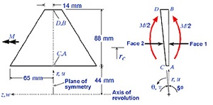
The bending moment M must be applied indirectly in the reduced model since we don't know a priori the circumferential stress distribution it produces on the cross-section. Instead, we'll prescribe displacements such that radial plane sections remain plane and a pure moment load acts on the model i.e. no net force acts on it. The moment M can be computed from the stress distribution on the cross-section obtained from FEA. Stresses scale linearly with the applied moment. So the stresses associated with a prescribed moment Mp can be obtained by multiplying the computed stresses by the ratio Mp/M.
The z-constant plane containing A,B,C and D is a symmetry plane. So only half the cross-section needs to be modeled.
Boundary Conditions
The nodal d.o.f. in the radial (u), circumferential (v), and axial (w) directions are constrained as follows:
...
Go to Step 1: Start-up and preliminary set-up