 Sign-up for free online course on ANSYS simulations!
...
Increase number of grid lines: Options > Grid Spacing ...
Unselect Auto for both x and y linear spacing.
Change X-axis linear spacing to 0.025 while retaining the axis limits: -0.05:0.025:0.45
Similarly, change Y-axis linear spacing to 0.01.
Click Apply and then Done.
...
![]()
offers a shortcut for creating a rectangle and is equivalent to the menu option we used for creating R1. Click on the rectangle icon. Click approximately near (0.1,0) and (0.3,0.05) to create R2. Modify coordinates:
Double-click on R2
Left: 0.1
Bottom: 0
Width: 0.2
Height: 0.05
OK
Look below the toolbar. You should see Set formula: R1+R2
You can go in and edit this formula. This facility allows you to arbitrarily add or subtract geometric components as necessary to create the final geometry.
Save: File > Save Geometry As
Filename: beam.m
This file can be read back into CSG Mesh Tool using File > Open
Create rectangle R3 by copying R1:
Select R1 by clicking once on it.
Copy R1: Edit > Copy
Paste R1: Edit > Paste ...
X-axis displacement: 0.3
OK
You should see that R3 has been added to Set formula. 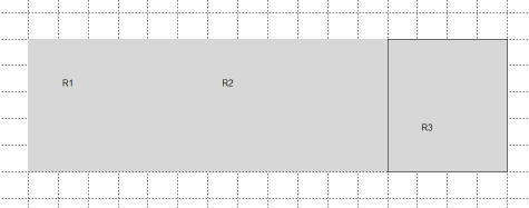
Check Boundaries
Click on the boundary icon: ![]()
This shows the boundaries of the geometry. The external boundaries are shown in red and internal boundaries in black. In the next step, we'll specify boundary conditions for the external boundaries.
Mesh Geometry
To initialize the mesh, click on the triangle icon: ![]()
To refine the mesh 2 times, select the multiple triangle icon twice:
![]()
Improve mesh quality: Mesh > Jiggle Mesh 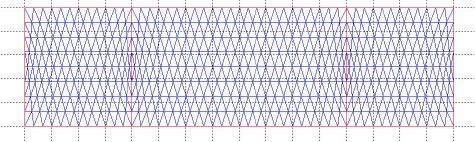
Are there nodes at the points where the boundary conditions need to be applied?
Save geometry: File > Save Geometry
Note that the manual for the CSG Tool can be accessed by selecting the Help button in the GUI.