 Sign-up for free online course on ANSYS simulations!
...
Enter the General Postprocessing module_:_
Main Menu > General Postproc
Plot Deformed Shape
Main Menu > General Postproc > Plot Results > Deformed Shape
Select Def + undeformed and click OK.
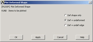
This plots the deformed and undeformed shapes in the Graphics window.
...
To save the deformation plot in a file, use Utility Menu > PlotCtrls > Hard Copy > To File. Select the file format you want and type in a filename of your choice under Save to: and click OK. The file will be created in your working directory. You can print out this file as necessary.
Animate the deformation:
Utility Menu > PlotCtrls > Animate > Deformed Shape
Select Def + undeformed and click OK. Select Forward Only in the Animation Controller.
Node 1 (Pin A) doesn't move and node 2 (Pin C) moves only in the vertical direction. Node 3 (Pin B) moves more or less in the direction of the applied force. The deformation of the structure agrees with the applied boundary conditions and matches with what one would expect from intuition. Stop the animation and close the animation control window.
Turn On Node and Element Numbers
In order to interpret the results that ANSYS reports, it's useful to turn on the node and element numbers in the Graphics window.
Utility Menu > PlotCtrls > Numbering
The Plot Numbering Controls menu is used to control the numbering of the various entities in a finite-element model.
Turn on Node numbers. Under Elem/Attrib numbering, select Element numbers. Click OK.
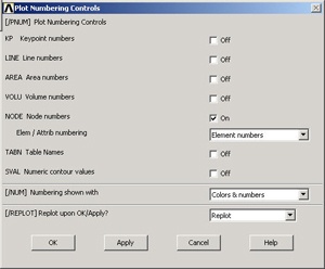
The node and element numbers will now appear in the Graphics window.
List Forces in Truss Members: Method 1
Main Menu > General Postproc > List Results > Element Solution
From the list, under Element Solution, select All Available force items . Click OK.
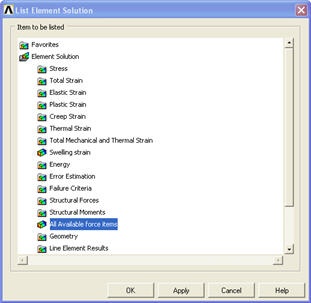
This brings up a window listing the forces that the elements apply on each of their nodes:
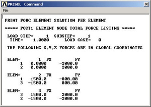
These element forces reported by ANSYS are forces ON its environment BY the element, not the converse. For example, Element 2 (or member AB) applies a force of 1500 N in the x-direction and 800 N in the negative y-direction on node 1 (or pin A). This means that the total force in AB is . The resultant acts from A to B i.e. the member is pulling on pin A. So it must be in tension. Similarly, the force in Element 1 (AC) is 2000 N (tension) and in Element 3 (BC) is 2500 N (compression). Note that your node and element numbers might be different from the above since they depend on the order in which the lines were created.
Close the PRESOL Command window.
List Forces in Truss Members
...
Bring up the help page for LINK1 element:
Utility Menu > Help > Help Topics
Under the Contents tab, select
Release 1011.0 Documentation for ANSYS > Element Elements Reference > Element Library > LINK1
In the LINK1 help page, scroll down to Table 1.1: LINK1 Element Output Definitions. You'll see the item. This table lists all the output items you can get for the LINK1 element. Let's scour this table for the element output that corresponds to the force in a truss member. We see the following item in the table that looks like a promising candidate:
MFORX: Member force in the element coordinate system X direction
The figure at the top of the LINK1 help page, reproduced below, shows that the x-direction in the element coordinate system is along the line. So element.
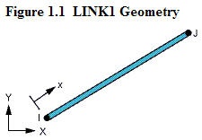
Thus, MFORX is basically the axial force in the element.
So how do we get the MFORX values for our three elements from ANSYS? ANSYS has a quirky way of doing this as we shall see. If you scroll down the help page further, you'll see the Table 1.2 LINK1 Item and Sequence Numbers with the following entry for MFORX:
MFORX SMISC 1
The output data for any element type is broken down into item groups with SMISC being one of the groups (SMISC stands for "Summable Miscellaneous" items). Each item within an item a group such as SMISC has an identifying "sequence" number. So, as per the above entry in Table 1.2, MFORX is an item in the item SMISC group with a sequence number 1. In effect, it's entry #1 in the SMISC group for the LINK1 element.
Minimize the help window. To list MFORX values, select:
Main Menu > General Postproc > List Results > Element Solution
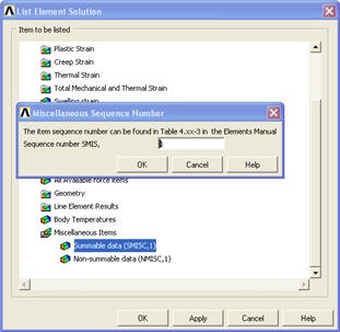
Under Element Solution, select Miscellaneous Items > Summable data (SMISC,1). Since MFORX is sequence number 1 in the SMISC group, enter 1 next to Sequent Sequence number SMIS in the editable field. Click OK. Click OK in the List Element Solution window.
This brings up a window with the axial forces in the elements. Positive values indicate tension and negative values compression. Do these values match what we got in method 1?

You can also plot the items listed under Element Output Definitions using the sequence number.
In most cases, you plot stresses using Main menu > General Postproc > Plot Results > Contour Plot >Nodal Solu. But for line elements like LINK1, this doesn't work and you'll get zero values for the stresses. So you'll have to use the sequence numbers to make stress plots for line elements.
List Reaction Forces at Nodes
Main Menu > General Postproc > List Results > Reaction Solu
Select All struc forc F for Item to be listed and click OK.
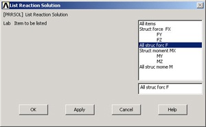
This brings up a window with the reaction forces at the nodes.
...
Close the PRRSOL Command window.
Go to Step 9: Validate the results
See and rate the complete Learning Module
...