 Sign-up for free online course on ANSYS simulations!
| Include Page | ||||
|---|---|---|---|---|
|
| Include Page | ||||
|---|---|---|---|---|
|
Start-Up
| HTML |
|---|
<iframe width="640" height="360" src="https://www.youtube.com/embed/Yug08tGTNNA" frameborder="0" allowfullscreen></iframe> |
Create Sketch
| HTML |
|---|
<iframe width="640" height="360" src="https://www.youtube.com/embed/-Gw21m4x73E" frameborder="0" allowfullscreen></iframe> |
Create Area
| HTML |
|---|
<iframe width="640" height="360" src="https://www.youtube.com/embed/6XX48cJH3Gg" frameborder="0" allowfullscreen></iframe> |
Save Project
| HTML |
|---|
<iframe width="640" height="360" src="https://www.youtube.com/embed/4W3dAjCooTs" frameborder="0" allowfullscreen></iframe> |
Check Your Understanding
Select true or false.
| Panel |
|---|
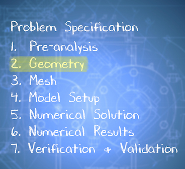
Problem Specification |
Step 2: Geometry
| Info | ||
|---|---|---|
| ||
If you would prefer to skip the geometry and mesh processes, then you can download the files here. Download the "zip" file, then "unzip" the file. Then, extract the "pipe_laminar" folder and the "pipe_laminar.wbpj" file to the desktop. Lastly, double click the "pipe_laminar.wbpj" file (located on the desktop) to launch ANSYS Workbench with the desired geometry and mesh files. Then, click here to skip ahead to Step 4 of the tutorial. |
...
https://confluence.cornell.edu/download/attachments/111221570/ScreenOrientation.PNG...
Creating a Sketch
Start by creating a sketch on the XYPlane. Under Tree Outline, select XYPlane, then click on Sketching right before Details View. This will bring up the Sketching Toolboxes.
...
https://confluence.cornell.edu/download/attachments/123547957/Select+Sketching+Toolboxes.gifClick on the +Z axis on the bottom right corner of the Graphics window to have a normal look of the XY Plane.
...
https://confluence.cornell.edu/download/attachments/111221570/Select+Normal+View.gifIn the Sketching toolboxes, select Rectangle. In the Graphics window, create a rough Rectangle from starting from the origin in the positive XY direction (Make sure that you see a letter P at the origin before you start dragging the rectangle. The letter P at the origin means the geometry is constrained at the origin.)
You should have something like this:
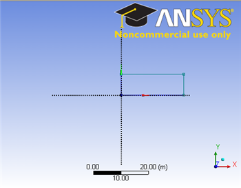
Note: You do not have to worry about geometry for now, we can dimension them properly in the later step.
Dimensions and Constraints
Now we will specify the appropriate dimensions and constraints.
Under Sketching Toolboxes, select Dimensions tab, use the default dimensioning tools. Dimension the geometry as shown:
insert geometry dimension
Under Details View on the lower left corner, input the value for dimension appropriately.
V1: 0.1 m
H2: 8 m
Now that we have the sketch done, we can create a surface for this sketch.
Concept>Surfaces From Sketches
This will create a new surface SurfaceSK1. Under Details View, select Sketch1 as Base Objects and then under Surface body select the thickness to 0.1m and click Apply. Finally click Generate to generate the surface.
You can close the Design Modeler and go back to Workbench (Don't worry, it will auto save).
Go to Step 3: Mesh