 Sign-up for free online course on ANSYS simulations!
...
Next, we step up to the plate to define the boundary conditions, namely, the displacement constraints and loads. Note that in ANSYS terminology, the displacement constraints are also "loads". We can apply the loads either to the geometry model or to the finite-element model (that is to the elements and nodes directly). The advantage of the former is that one doesn't have to re-specify the constraints on changing the mesh. So we'll apply the constraints to the geometry i.e. to the keypoints.
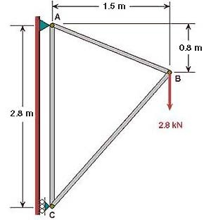
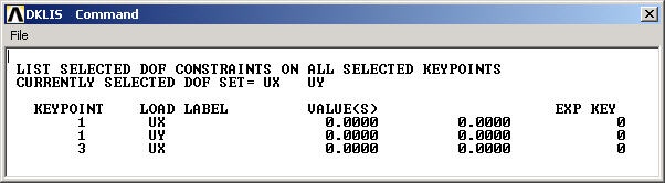
You can see from the diagram that the pin at A is constrained in x and y directions; or equivalently, keypoint 1 is constrained such that its UX and UY displacements are zero. Similarly, keypoint 3 is constrained such that its UX displacement is zero.
...
This brings up the Apply U, ROT on KPs pick menu.
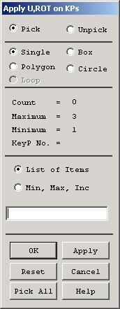
In the Graphics window, click on keypoint 1;
This will draw a small square around keypoint 1 to indicate that it's been picked.
In the pick menu, click Apply_._ The following menu shows up.
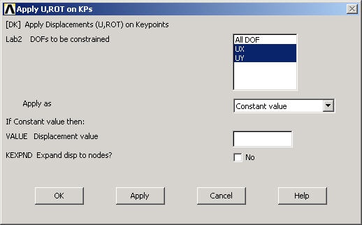
Since we want to constrain UX as well as UY to zero at keypoint 1, select both UX and UY from items in DOFs to be constrained list. Since the Displacement value is zero by default, leave that field empty. Click on Apply.
...
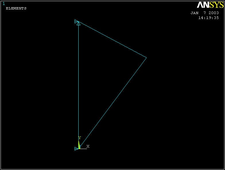
You will see a triangle symbol appear indicating that only the UX DOF is constrained at keypoint 3.
Close the Displacement and Apply menus.
...
This brings up a window with the constraint information.
If you made a mistake in applying a constraint, you can delete and reapply it. You can delete a constraint using Main Menu > Preprocessor > Loads > Define Loads >Delete > Structural > Displacement > On Keypoints. Alternately, you can resume from your last save and continue from there.
...
Enter -2800 for Force/ moment value. Click OK.
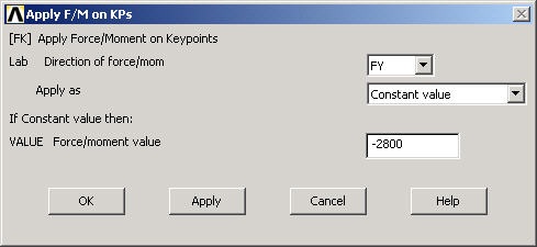
The negative sign for the force indicates that it is in the negative y-direction. You'll see a vector indicating the applied force in the Graphics window.
...