 Sign-up for free online course on ANSYS simulations!
| Include Page | ||||
|---|---|---|---|---|
|
| Include Page | (Tutorial Name) - Panel | (Tutorial Name) - Panel |
|---|
Geometry
...
|
Geometry
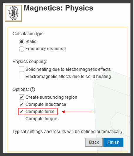
You will be prompted to either Define new geometry, Import geometry file, or Connect to active CAD session. Select Import new geometry and downloaded the file here. AIM will prompt again asking to select your calculation type, physics coupling and options. Under Options, check Compute force and then click Finish.
Creating geometric parameters
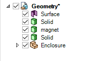
In order to vary the horizontal distance between the coil and magnet a parameter must be created. Once AIM has loaded click on Geometry > Edit Geometry. Hide the enclosure by deselecting the checkmark.
Triple click on the magnet to select the body. Select the Move tool and click on the origin.

Drag the origin onto the face of the magnet closest to the spool.
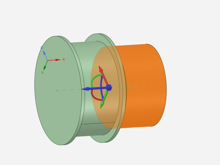
Once the origin turns into a square, select the blue axis of the Move tool. The other axis will be greyed out and in the General sidebar select the Ruler tool. The Ruler tool will then follow the cursor, at which point click the face of the spool closest to the inside the gap.

To create the parameter, click on the P next to the highlighted dimension box. Once the parameter is created, click the x in the top right corner to begin the physics set up.
...
Go to Step 3: MeshPhysics Setup
Go to all ( ANSYS or FLUENT) AIM Learning Modules