 Sign-up for free online course on ANSYS simulations!
...
Using ANSYS, plot the deflection, bending moment, and shear force distribution of the beam. If you have four elements, what is the optimal mesh? Repeat the solution with an eight-element mesh. Comment on the results. Is your solution right? How can you improve the finite element solution?
- What are the displacement and rotation constraints that need to be applied in your ANSYS model so that you don't get the solver pivot error?
- What is the total no. of degrees of freedom that ANSYS puts in for the four-element mesh?
- Bending moment: Trend from A to Ba. Do you expect linear, quadratic or cubic variation?b. Does the ANSYS solution within each elementshow this trend? Why or why not?
Tips:
- In ANSYS, you need to specify E and I separately. You can pick them independently as long as you get the desired EI. You specify I by specifying the cross-section as we saw in the preceding tutorial. You can pick E=2e11 (default) and calculate the equivalent square cross-section.
- Model the geometry using four lines. You will need to have vertices where you will be applying forces, moments or displacement constraints. You can sketch four lines using Draw > Polyline. Right-click and select Open End to end the polyline.
- Apply a distributed load using Line Pressure (see snapshot further down this page). In version 17, you can select all four lines when applying the line pressure. But in version 16 and prior versions, when you apply the line pressure, you can select only one line at a time. Since there are four lines in total, you'll need to apply line pressure four times.
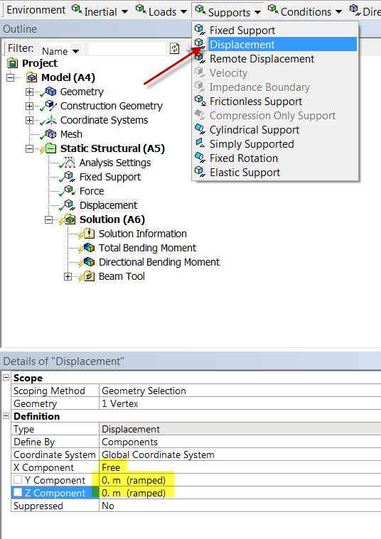
- Apply the simply supported constraints using Supports > Displacement. For example, the settings in the figure below can be used to apply the simply supported constraint at A or C. As we saw in the tutorial, ANSYS uses a generalized 3D beam formulation which includes z displacements. Since we don't have any displacement in the z direction, you can set the z displacement to zero. You really need to do this at two vertices only. This will prevent the beam from translating in the z-direction and rotating about the y-axis. Even though we don't have any forces in the z-direction, the numerical solution in effect introduces tiny forces in the z-direction due to discretization and round-off errors. We have to add additional constraints to ensure that these tiny forces cannot cause translations in z and rotations about y. Otherwise, the problem becomes ill-posed, the stiffness matrix cannot be inverted and ANSYS will report a vague "solver pivot error".
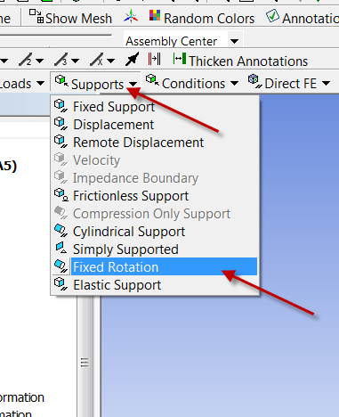
- You also need to add a constraint to prevent rotation about the x axis due to tiny torques from numerical error. This can be done by selecting Supports > Fixed Rotation as shown below.
...