 Sign-up for free online course on ANSYS simulations!
...
- In ANSYS, you need to specify E and I separately. You can pick them independently as long as you get the desired EI. You specify I by specifying the cross-section as we saw in the preceding tutorial. You can pick E=2e11 (default) and calculate the equivalent square cross-section.
- Model the geometry using four lines. You will need to have vertices where you will be applying forces, moments or displacement constraints.
- Apply a distributed load using Line Pressure (see snapshot further down this page). When you apply line pressure, you can select only one line at a time. Since there are four lines in total, you need to apply line pressure four times.
- Apply the simply supported constraints using Supports > Displacement. For example, the settings in the figure below can be used to apply the simply supported constraint at A or C. As we saw in the tutorial, ANSYS uses a generalized 3D beam formulation which includes z displacements. Since we don't have any displacement in the z direction, you can set the z displacements in simply supported conditions displacement to zero.
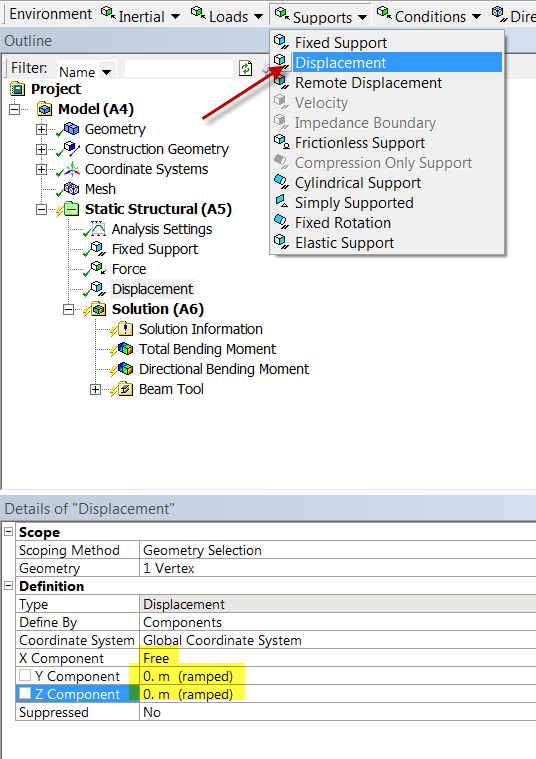 . You really need to do this at two vertices only. This will prevent the beam from translating in the z-direction and rotating about the y-axis. Even though we don't have any forces in the z-direction, the numerical solution in effect introduces tiny forces in z-direction due to discretization and round-off errors. We have to add additional constraints to ensure that these tiny forces cannot cause translations in z and rotations about y. Otherwise, the problem becomes ill-posed, the stiffness matrix cannot be inverted and ANSYS will report a vague "solver pivot error".
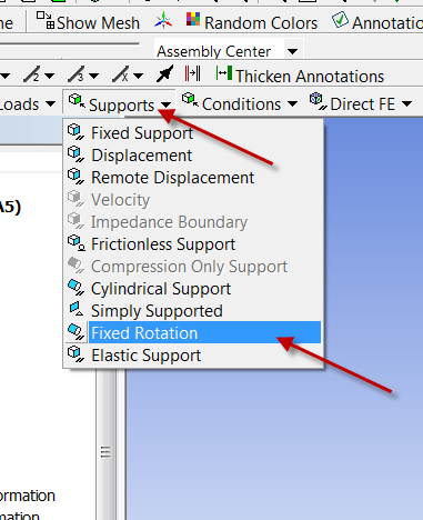
 - You also need to add a constraint to prevent rotation about the x axis due to tiny torques from numerical error. This can be done by selecting Supports > Fixed Rotation as shown below.
 In the ANSYS model , you have to add an extra constraint by fixing the rotations about x and y axes at the right end (see snapshots below). Otherwise you might get a solver pivot error. This is because ANSYS is using a 3D beam element with these additional rotations as dof's. Adding the fixed rotation will zero out these additonal dof's.
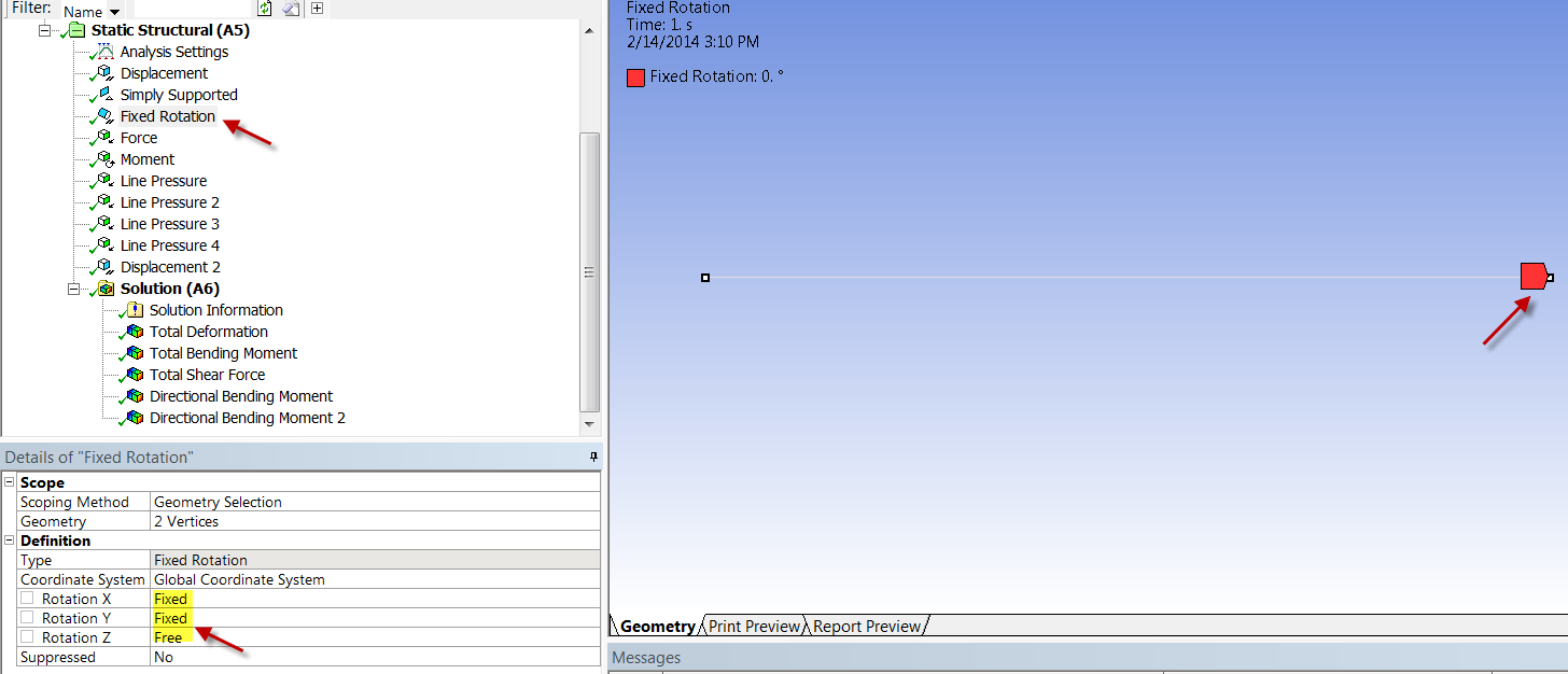
Exercise 2: Distributed Load
...