 Sign-up for free online course on ANSYS simulations!
...
- Determine the flow behavior over a Vertical Axis Wind Turbine
- Apply concepts of Moving Frame of Reference in FLUENT to simplify a transient problem into a steady state situation
- IN NEXTS: creating multiple parts mesh and use in Sliding Mesh
| Note |
|---|
Under Construction |
- Mesh

Problem Specification
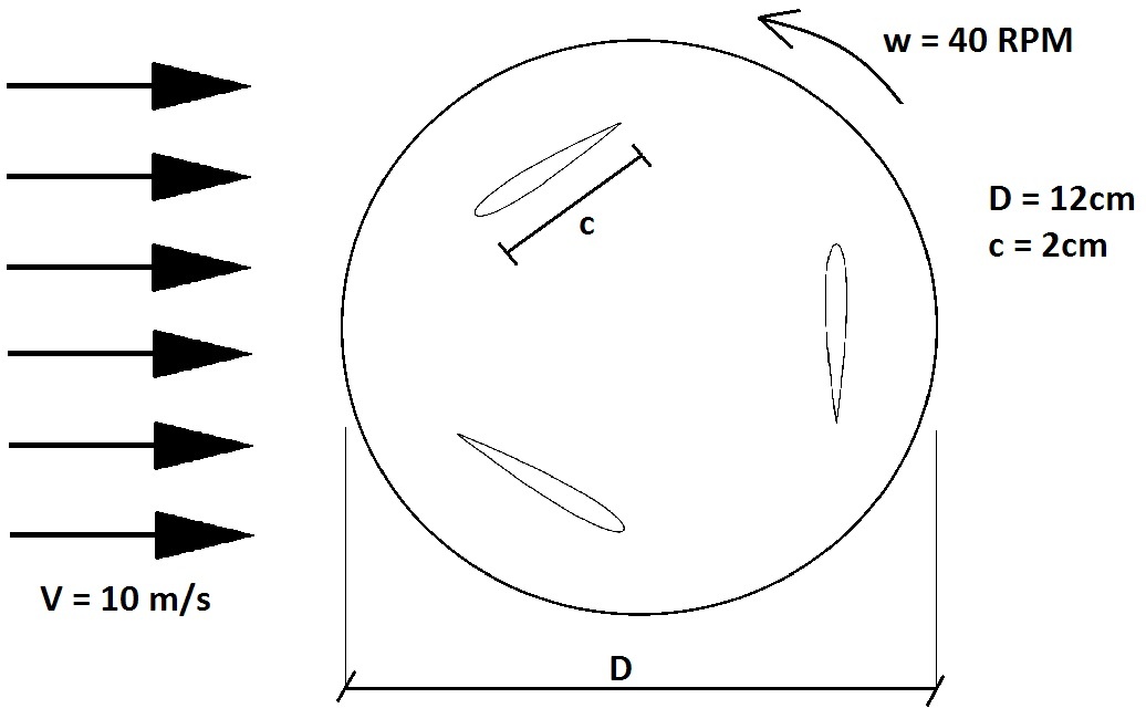
Consider an uniform flow of V = 10m/s passing through a Vertical Axis Wind Turbine (VAWT) as sketched above. The VAWT has a diameter of 12cm and 3 equally spaced blades, each one with a chord length of 2cm. For simplification, consider that it spins with a constant angular velocity of 40 RPM*
| Note |
|---|
Under Construction |
Simplification : No airfoil, but flat plat with 20deg angle of attack
Picture of an actual VAWT.
Drawing, explain the simplifications (2D, etc).
.
You may use the following simplifications:
- Assume the airfoils are flat plates of 0.1x2cm, positioned on a pitch angle of 20deg, i.e. the plates are placed such that when they are at the upper-most part its trajectory, they form an angle of 20deg with the horizontal.
- Incoming flow with a constant profile of 10m/s
- The downstream pressure is 101325 Pa.
- Air with density of 1.225kg/m3 and viscosity of 1.7894e-5 Pa.s.
- 2D analysis
![]() Picture of an actual VAWT
Picture of an actual VAWT ![]() Specify diameter, number of blades, size of plates, angular velocity, incoming wind speed,
Specify diameter, number of blades, size of plates, angular velocity, incoming wind speed,
Solve this problem numerically using ANSYS FLUENT. Present the following results:
Velocity magnitude contours
Pressure contours
Velocity profile at the outletoutlet
Torque
- NEXT: animation, etc
Torque
Describe what happen downstream of the turbine and think on how that would affect following turbines. Array.an array of VAWT.
* Note that this is an important simplification. Here we're considering that the turbine is already spinning independently of the flow, what is clearly not true, since the flow is responsible for spinning the turbine. There is only one stable combination of incoming flow velocity and RPM, given the geometry and mass of the turbine. However, modeling the movement of a geometry caused by the flow is extremely advancedconsiderably difficult, and require use of a method called "6DOF solver". A tutorial on that will be made in the future. For now, let's stick simpler analysis, first a steady state picture of the problem (this tutorial), and later a transient analysis (future tutorial).
...