 Sign-up for free online course on ANSYS simulations!
| Include Page | ||||
|---|---|---|---|---|
|
| Include Page | ||||
|---|---|---|---|---|
|
Vertical Axis Wind Turbine - Part 1
Created using ANSYS 16.2
This tutorial has two parts. The first part will analyse the flow using Moving Frame of Reference, while the second part will use the Sliding Mesh feature.
| Info |
|---|
To access Part 2 of the tutorial, click here |
Learning Goals
In this tutorial, you will learn to:
- Determine the flow behavior over a Vertical Axis Wind Turbine
- Apply concepts of Moving Frame of Reference (part 1) and Sliding Mesh (part 2) in FLUENT to simplify a transient problem into a steady state situation
- IN NEXTS: creating multiple parts mesh and use in Sliding Mesh
| Note |
|---|
Under Construction |
Problem Specification
Problem Specification
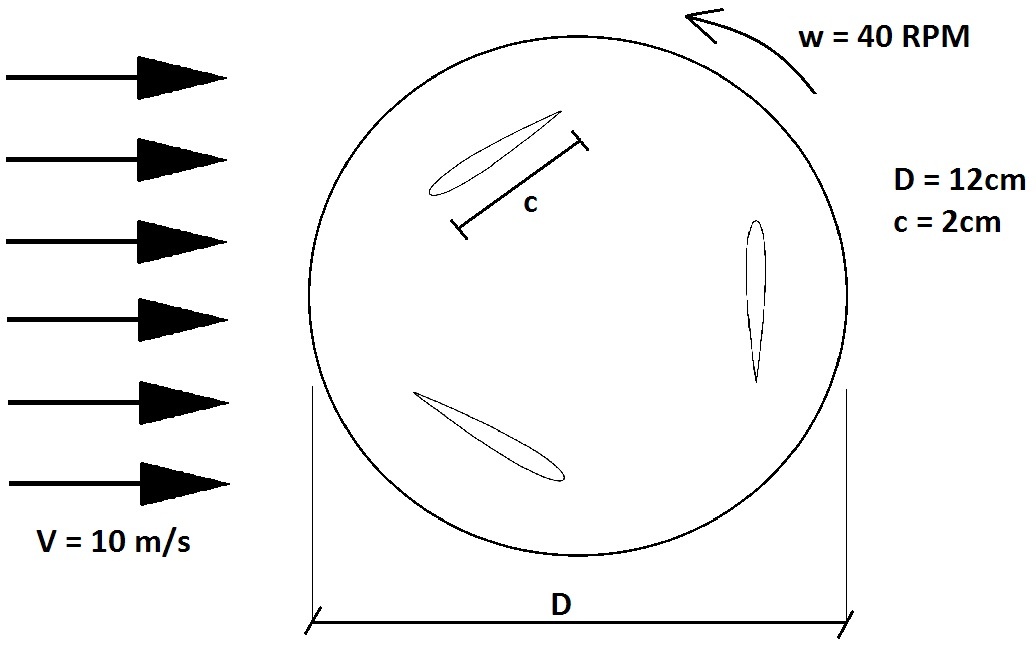
Consider a uniform flow of V = 10m/s passing through a Vertical Axis Wind Turbine (VAWT) as sketched above. The VAWT has a diameter of 12cm and 3 equally spaced blades, each one with a chord length of 2cm. For simplification, consider that it spins with a constant angular velocity of 40 RPM*. The center of each blade is located 0.04m from the center of the hub.
Note that this is a Darrieus VAWT, which is Lift based; in contrast to the Savonius VAWT, which is Drag based. This is an intensive field of research, and at Cornell we have the Fluid Dynamics Research Laboratory, directed by Prof. Charles Williamson. In the last section, we will compare results with the experimental data obtain by the lab.
* Note that this is an important simplification. Here we are considering that the turbine is already spinning independently of the flow, which is clearly not true, since the flow is responsible for spinning the turbine. There is only one stable combination of incoming flow velocity and RPM, given the geometry and mass of the turbine. However, modeling the movement of a geometry caused by the flow is considerably difficult, and requires the use of a method called "6DOF solver". A tutorial on that is intended to be made in the future. For now, let's stick to a simpler analysis, first a steady state picture of the problem (this tutorial), and later a transient analysis (part 2 of this tutorial).
...
Go to Step 1: Pre-Analysis & Start-Up
Go to all (ANSYS or FLUENT ) Learning Modules