...
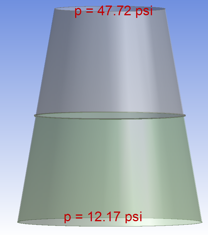
The pressure due to the exhaust gas in the nozzle is calculated using 1D gas dynamics. It is assumed to vary linearly in along the axial directionnozzle axis. The pressure values at the top and bottom of our model are indicated in the image below.
The regeneration channels are omitted in the model. In exchange, a free body diagram is used to deduce the equivalent forces on the mid nozzle and lower nozzle (the upper nozzle is not modeled here). This force pair is modeled as two separate forces.
The details of the load calculations using publicly available data are provided in this Excel file <<<include link>>>.
Go to Step 1: Pre-Analysis & Start-Up
...
 Sign-up for free online course on ANSYS simulations!