 Sign-up for free online course on ANSYS simulations!
| Include Page | ||||
|---|---|---|---|---|
|
| Include Page | ||||
|---|---|---|---|---|
|
...
Spacecraft Assembly with a Bolted Flange
Created using ANSYS (Version Number)16.1
| Note |
|---|
This module is under construction |
Learning Goals
In this tutorial, you will learn to:
- Build a nonlinear finite-element model to analyze a bolted assembly
- Model contacts between parts in an assembly
- Model thermal strains
- Model temperature-dependent material properties
- (e.g.: Determine the displacements and stresses in a bike crank using 3D FEA capabilities in ANSYS Mechanical)
- (e.g.: Verify the finite-element results from ANSYS model by refining the mesh and also comparing with hand calculations)
| Note |
|---|
Under Construction |
Problem Specification
Problem Specification
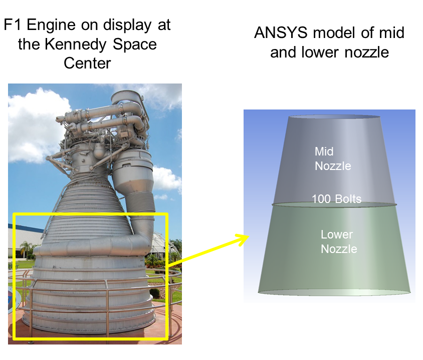
The Saturn V rocket that carried people to the moon is the most powerful machine ever built. Watch this awe-inspiring video to get a sense of the tremendous power packed into this rocket. The Saturn V's first stage was powered by five F1 engines. In this exercise, we analyze the bolted flange joint that connected the mid and lower parts of the F1 engine nozzle. The image below shows a picture of the F1 engine and the corresponding model in ANSYS. Note that the ANSYS model includes only the mid and lower parts of the nozzle and the bolted flange joint connecting them.
Below is close-up view of the bolted flange joint connecting the mid and lower parts of the nozzle.
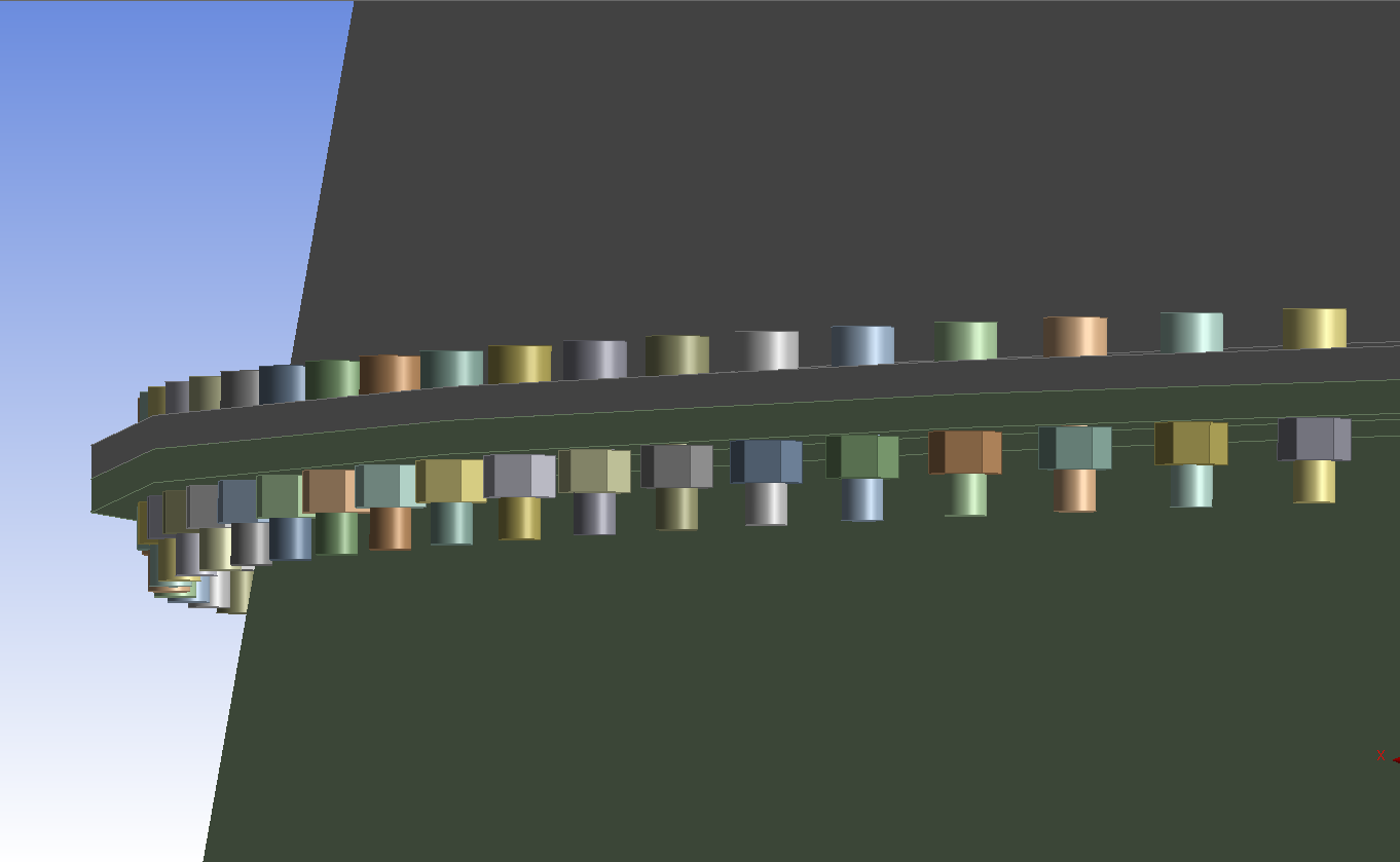
We'll analyze this bolted joint by building a non-linear finite element model in ANSYS. Our main objective is to assess the margin of safety of the flange bolts. We'd also like to determine the gaps that develop between the jointed parts when the assembly is loaded.
The pressure due to the exhaust gas in the nozzle is calculated using 1D gas dynamics. It is assumed to vary linearly along the nozzle axis. The regeneration channels are omitted in the model. In exchange, a free body diagram is used to deduce the equivalent forces on the mid nozzle and lower nozzle (the upper nozzle is not modeled here). This force pair is modeled as two separate forces. The gas temperature is 700 F which causes thermal strain. The bolt is pre-loaded to 50% of its breaking strength.
The video above <<<link>>> discusses the calculation of model inputs. The details of the load calculations are provided in this Excel file <<<link>>>.
...
Go to Step 1: Pre-Analysis & Start-Up
Go to all ( ANSYS or FLUENT) Learning Modules