 Sign-up for free online course on ANSYS simulations!
...
| Info |
|---|
To access Part 1 of the tutorial, click here. |
Problem Specification
Overview
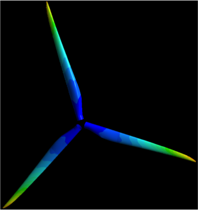
This tutorial considers the deformation due to aerodynamic loading of a wind turbine blade by performing a steady-state 1-way FSI (Fluid-Structure Interaction) analysis. Part 1 of the tutorial uses ANSYS Fluent to develop the aerodynamics loading on the blade. In part 2, the pressures on the wetted areas of the blade are passed as pressure load loads to ANSYS Mechanical to determine stresses and deformations on the blade.
The blade is 42.3 meters long and starts with a cylindrical shape at the root and then transitions to the airfoils S818, S825 and S826 for the root, body and tip, respectively. This blade also has pitch to vary as a function of radius, giving it a twist and the pitch angle at the blade tip is 4 degrees. This blade was created to be similar in size to a GE 1.5XLE turbine. For more information on the dimension characteristics of this blade, please see this M.Eng report (note that model in the present tutorial has an additional 2 meter cylindrical extension at the root to make it more realistic).
The blade is made out of an orthotropic composite material, it has a varying thickness and it also has a spar inside the blade for structural rigidity. These specs, which are important for the FEA simulation, are described in more details below. in Part 2 of the tutorial.
The turbulent wind is coming from flows towards the negative z-direction at (into the page on the above diagram) at 12 m/s which is a typical rated wind speed for a turbine this size. This incoming flow makes the blade rotate at an angular velocity of -2.22 rad/s about the z-axis (the blade is thus spinning clockwise when looking at it from the front, like most real wind turbines). The blade root is offset from the axis of rotation by 1 meter to make it more represenetative of an actual turbine where the blades would connect to the hub. Note that the Note that to represent the blade being connected to a hub, the blade root is offset from the axis of rotation by 1 meter to represent the blade being connected to a hub.
...
...
Under Construction
...
Part 2
This section involves the solid mechanics aspects of this wind turbine blade tutorial. The pressures load found using Fluent in Part 1 are imported in Mechanical and the stresses and deformations on the blade are subsequently determined.
...
These thicknesses are actually very close to what you would encounter on a real turbine. ANSYS recently wrote a joint paper with GE about an FSI simulation on one of their blades a blade and they provided us with these values that are close to the real deal.
Both parts are made out of an orthotropic composite material with the following properties:
...
Similarly, these values were given to us by ANSYS and they are also very representative of composite properties found found in real wind turbinesturbine blades.
...
Let's get started!
Go to Step 1: Pre-Analysis & Start-Up
...