 Sign-up for free online course on ANSYS simulations!
...
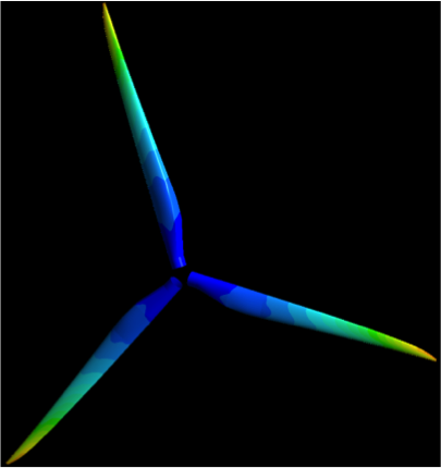
The blade is composed of an outer surface and an inner spar. The thickness of the outside surface linearly decreases from 0.1 m at the root to 0.005 m at the tip. The spar has a similar thickness behavior with 0.1 m at its closest point to the root and 0.03 m at the tip. To sum up, here are the thickness specifications needed along with their location with respect to the global coordinate system (which represents the center of an imaginary hub and thus the center of rotation).
Surface
| X (m) | Thickness (m) |
|---|---|
| -1 | 0.1 |
| -44.2 | 0.005 |
...
| X (m) | Thickness (m) |
|---|---|
| -3 | 0.1 |
| -44.2 | 0.03 |
These thicknesses are actually very close to what you would encounter on a real turbine. ANSYS recently wrote a joint paper with GE about an FSI simulation on one of their blades and they provided us with these values that are close to the real deal.
Both parts are made out of an orthotropic composite material with the following properties:
...
Density (kg/m^3) | 1550 |
|---|---|
Young's Modulus-X (Pa) | 1.1375E+11 |
Young's Modulus-Y (Pa) | 7.583E+09 |
Young's Modulus-Z (Pa) | 7.583E+09 |
Poisson's Ratio-XY | 0.32 |
Poisson's Ratio-YZ | 0.37 |
Poisson's Ratio-XZ | 0.35 |
Shear Modulus-XY (Pa) | 5.446E+09 |
Shear Modulus-YZ (Pa) | 2.964E+09 |
Shear Modulus-XZ (Pa) | 2.964E+09 |
Similarly, these values were given to us by ANSYS and they are also very representative of composite properties found in real wind turbines.
| Note |
|---|
Under Construction |
...