 Sign-up for free online course on ANSYS simulations!
| Include Page | ||||
|---|---|---|---|---|
|
| Include Page | ||||
|---|---|---|---|---|
|
3D Finite-Element Analysis of a Bike Crank
Created using ANSYS 14.5
Learning Goals
In this tutorial, you will learn to:
- Determine the displacements and stresses in a bike crank using 3D FEA capabilities in ANSYS Mechanical
- Verify the finite-element results from ANSYS by refining the mesh and also comparing with hand calculations
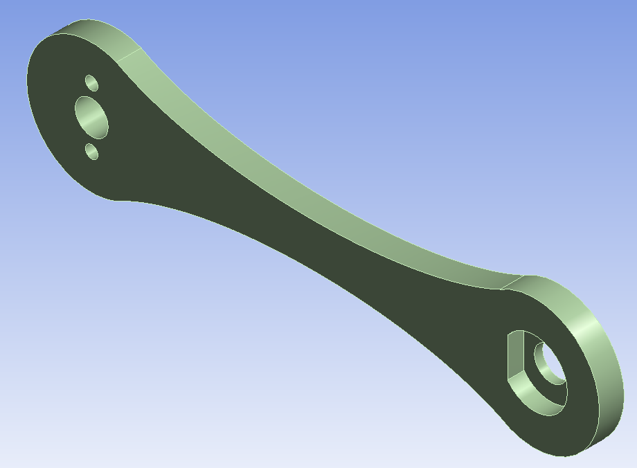
Problem Specification
Consider the following bike crank model.
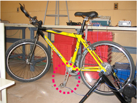
To orient ourselves, the following figure shows the location of a similar bike crank mounted on a bicycle.
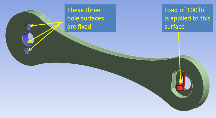
Material properties: The bicycle crank's material is aluminum 6061-t6. The Young's modulus is 10,000 ksi, and the Poisson's Ratio is .33.
Boundary conditions: Apply a load of 100 lbf in the y-direction on the right hole surface and fix the 3 left hole surfaces as shown below. Note that this is an approximation of the actual loads and constraints on the bike crank.
Using ANSYS Mechanical, determine the following:
- Deformed shape
- Displacement field
- Stress distribution
Wiki Markup {latex}$\sigma_x(x,y,z)${latex}