 Sign-up for free online course on ANSYS simulations!
| Include Page | ||||
|---|---|---|---|---|
|
| Include Page | ||||
|---|---|---|---|---|
|
Pre-Analysis & Start-Up
...
Reference* S. Timoshenko and J.N. Goodier: "Theory “Theory of Elasticity" Elasticity” -- Chap. 13: Sect. 125, "“Pressure between Two Spherical Bodies in Contact"
...
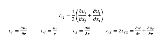
Second relationship is called Hooke's Hooke’s law. For our model, we assume isotropic material under plane stress, and so further simplifying the Hooke's Hooke’s law results in the following equations.
...
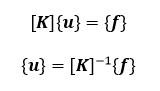
Each of the eight nodes shown above can be described by displacement vectors (translational and rotational components, depending on the element type) and by force vectors. Finite element method first solves for the nodal displacement field with the specified boundary conditions. The underlying system of equations that ANSYS solves for is shown below.
 unmigrated-wiki-markup
Here, \ [*K*\] is also referred to as the global stiffness matrix, and contains _n_ by _n_ components, where _n_ is equal to the total degrees of freedom of the system. On the other hand, {*u*} and {*f*} are column matrices with _n_ components, which represent nodal displacement fields and nodal force fields, respectively. After specifying the appropriate boundary condition in ANSYS, it then solves for these displacement and force fields ] is also referred to as the global stiffness matrix, and contains n by n components, where n is equal to the total degrees of freedom of the system. On the other hand, {u} and {f} are column matrices with n components, which represent nodal displacement fields and nodal force fields, respectively. After specifying the appropriate boundary condition in ANSYS, it then solves for these displacement and force fields simultaneously.
However, in the case of our Hertz contact example, we note that the system is a highly nonlinear problem, due to the mechanical interactions between multiple components of the system. The fact that the boundary condition at the contact interface between the sphere and the rigid plate changes throughout the loading process indicates that an iterative approach is necessary to converge the solutions. More specifically, we observe that the state of traction and the stiffness of the system depend on the displacement near the contact interface.
...
The following video shows how to create a project and set up Engineering Data for our problem.
| Wiki Markup |
|---|
{html} |
| HTML |
<iframe width="600" height="450" src="//www.youtube.com/embed/08WNUUN1c8Q?rel=0" frameborder="0" allowfullscreen></iframe>{html} |