 Sign-up for free online course on ANSYS simulations!
| Include Page | ||||
|---|---|---|---|---|
|
| Include Page | ||||
|---|---|---|---|---|
|
Wind Turbine Blade FSI (Part 1)
Created using ANSYS 1415.50
| Info |
|---|
To access Part 2 of the tutorial, click here. |
...
This tutorial considers the deformation due to aerodynamic loading of a wind turbine blade by performing a steady-state 1-way FSI (Fluid-Structure Interaction) analysis. Part 1 of the tutorial uses ANSYS Fluent to develop the aerodynamics loading on the blade. In part 2, the pressures on the wetted areas of the blade are passed as pressure load to ANSYS Mechanical which performs the Computational Structural Mechanics (CSM) to determine stresses and deformations on the blade.
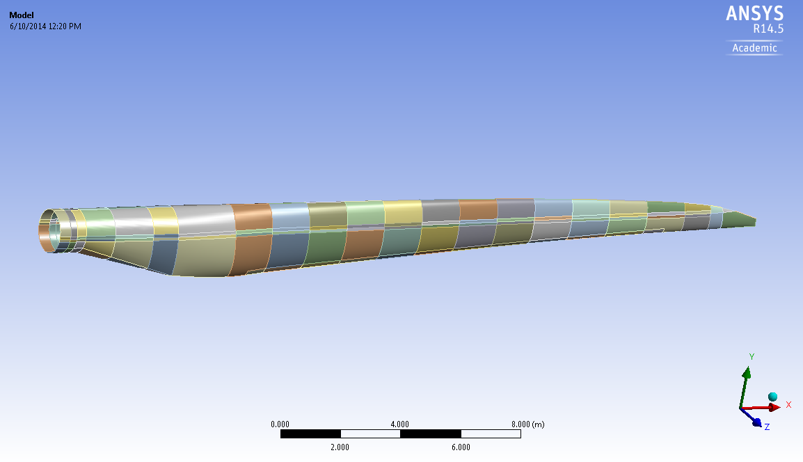
The blade is 27m long with a rotational angular velocity of 2.43 rad/s. The upstream wind speed (or should we say the free stream velocity?) is 8 m/s. The 42.3 meters long and starts with a cylindrical shape at the root and then transitions to the airfoils S818, S825 and S826 for the root, body and tip, respectively. This blade also has a varying pitch as a function of radius, which gives it a twist and the pitch angle at the blade tip is 4 degrees. This blade was created to be similar in size to a GE 1.5X turbine. For more information on the dimension characteristics of this blade, please see this M.Eng report (note that model in the present tutorial has an additional 2 meter cylindrical extension at the root to make it more realistic). The blade is made out of an orthotropic composite material with the following properties: (Should we include all this info here or only in Part 2?)
Density (kg/m^3) | 1550 |
|---|---|
Young's Modulus-X (Pa) | 1.1375E+11 |
Young's Modulus-Y (Pa) | 7.583E+09 |
Young's Modulus-Z (Pa) | 7.583E+09 |
Poisson's Ratio-XY | 0.32 |
Poisson's Ratio-YZ | 0.37 |
Poisson's Ratio-XZ | 0.35 |
Shear Modulus-XY (Pa) | 5.446E+09 |
Shear Modulus-YZ (Pa) | 2.964E+09 |
Shear Modulus-XZ (Pa) | 2.964E+09 |
*Include more details on the boundary conditions?
Option #2 (almost exact copy of Edwin's text):
This steady-state 1-way FSI (Fluid-Structure Interaction analysis that uses Fluent+Mechanical) example considers the deformation due to aerodynamic loading of a wind turbine blade. The blade is 27m long with a rotational velocity of 2.43 rad/s. The upstream wind speed is 8 m/s. The Computational Fluid Dynamics (CFD) is performed using ANSYS Fluent to develop the aerodynamic loading on the blade (Part 1 of this tutorial). The pressure on the wetted areas of the blades are the passed as a pressure load in ANSYS Mechanical which performs the Computational Structural Mechanics (CSM) to determine stresses and deformations on the blade (Part 2 of this tutorial).
, it has a varying thickness and it also has a spar along the length of the blade for structural rigidity. These are further described in Part 2 of the tutorial.
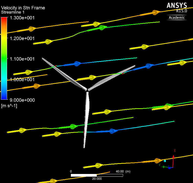
This blade is spinning at an angular velocity of -2.22 rad/s with respect to the incoming wind (the blade is thus spinning clockwise like most real wind turbines). The upstream wind speed (or should we say the free stream velocity?) is 12 m/s (a typical rated wind speed for a turbine this size) (say something about it being turbulent?. This blade therefore has a tip speed ratio, which is the ratio of tip velocity to incoming wind, of 8 (also a typical value).
Material??
| Note |
|---|
Under Construction |
Part 1
In this section of the tutorial, the blade geometry is imported, a mesh is created around the blade and Fluent is then used to find the aerodynamics loading on the blade. Here's some more information about the set-up.
Solver: Pressure-based
Viscous model: k-omega SST
Fluid: Air at standard conditions (15 degree celcius). It has density of 1.225 kg/m^3 and viscosity of 1.7894e-05 kg/m*s
The boundary conditions for this problem are as follow.
Inlet:
| Note |
|---|
Under Construction |
Go to Step 1: Pre-Analysis & Start-Up
...