 Sign-up for free online course on ANSYS simulations!
...
Now, we will set up a result object for the bending moment along the beam. We will do this by setting up a "path" along the line body. To set up a path, click on  in the Outline window. This will launch the Model toolbar in the Menu Bar. In the Model toolbar, press
  which will bring up the Construction Geometry Tool bar, then press
  to create a path.
...
Now that we have created the path, we need to create the solver for the a solution object that gives the bending moment along the beampath. Click on  in the Outline window to bring up the solution menu, then select Beam Results > Bending Moment. Now that we created the solution, we need to change the parameters so it solves along the path we created.
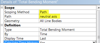
In the Details of "Total Bending Moment" window, change Scoping Method to Path. Next, define the Path parameter to neutral axis (the path we created). 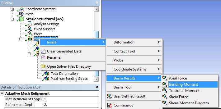
click here for full view
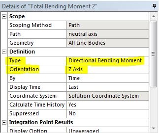
Directional Bending Moment
We would also like to look at the bending moment in a specific direction. Repeat the above step steps to setup another bending moment solutionresults object. In the detail details window of the new bending moment, change the type to Directional Bending Moment instead of the default Total Bending Moment. Change the orientation to Z axis.
Solve
In order to solve, click on the solve button,  , which is located near the top of the Setup window. This process may take some time depending on the quality of the computer you are working with, so please be patientANSYS will obtain the numerical solution where the ANSYS solver will form the stiffness matrix for each beam element, assemble them into the global stiffness matrix and invert it to get the nodal displacements and slopes. It will then extract the requested results and populate the results objects in the tree.
Go to Step 6: Numerical Results
...