 Sign-up for free online course on ANSYS simulations!
...
Boundary Conditions
In Boundary Conditions, because this is a turbulent model, all turbulence parameters must be specified on the boundaries.
Click to edit "air" (a velocity inlet). Change the velocity specification method to Components, and set the axial velocity at 10m/s. Adjust the turbulence parameters as in the dialogue. Press OK once all the changes have been made. 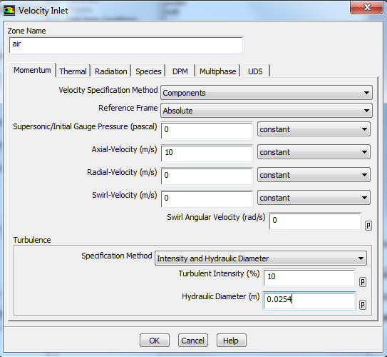
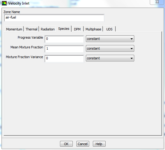
Similarly, edit the air-fuel boundary to have velocity components, with 50m/s axial velocity and 30m/s swirl velocity. The turbulent intensity should be 10%, and the hydraulic diameter should again be 0.0254m. Clicking to the Species tab, change the mixture fraction to 1.0. This is because this stream will be taken as the fuel stream, whereas the previous air boundary did not need to be set beyond the default value of 0 for the oxidizer stream. 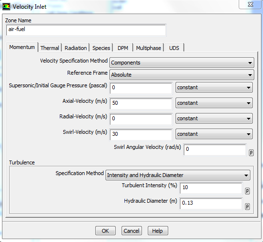
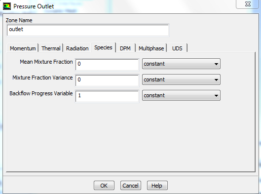
Edit the outlet boundary condition, which is a pressure outlet. Use 10% for Backflow Turbulent Intensity, and 0.13m for the Backflow Hydraulic Diameter. Clicking to the Species tab, change the Backflow Progress Variable to 1. This means that the boundary condition where the progress variable is 1.0 will only be applied in the case that there is backflow from this outlet. 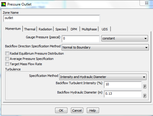
Go to Step 5: Numerical Solution
...