 Sign-up for free online course on ANSYS simulations!
| Include Page | ||||
|---|---|---|---|---|
|
| Include Page | ||||
|---|---|---|---|---|
|
Wind Turbine Blade FSI (Part 2)
...
| Info |
|---|
This module is from our free online simulations course at edX.org (sign up here). The edX interface provides a better user experience and the content has been updated, so we recommend that you go through the module there rather than here. Also, you will be able to see answers to the questions embedded within the module there. |
Created using ANSYS 15.0
| Note |
|---|
This tutorial has videos. If you are in a computer lab, make sure to have head phones. |
| Info |
|---|
To access Part 1 of the tutorial, click here. |
Problem Specification
Overview
...
This tutorial considers the deformation due to aerodynamic loading of a wind turbine blade by performing a steady-state 1-way FSI (Fluid-Structure Interaction) analysis. Part 1 of the tutorial uses ANSYS Fluent to develop the aerodynamics loading on the blade. In part 2, the pressures on the wetted areas of the blade are passed as pressure load loads to ANSYS Mechanical which performs the Computational Structural Mechanics (CSM) to determine stresses and deformations on the blade.
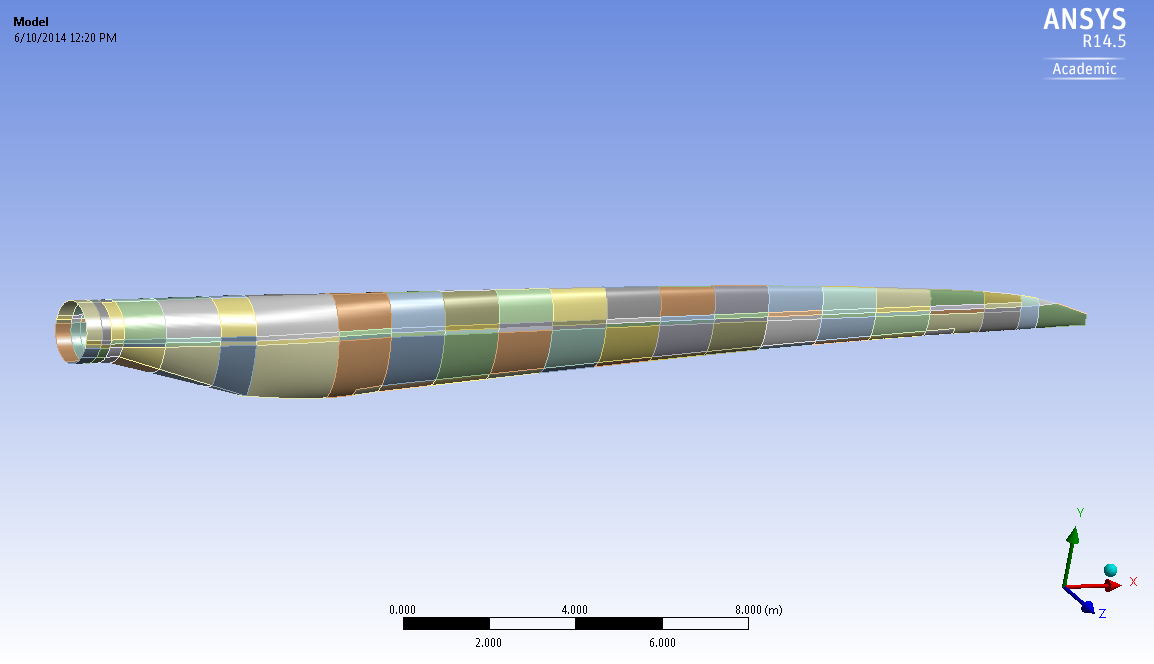
The blade is 42.3 meters long and starts with a cylindrical shape at the root and then transitions to the airfoils S818, S825 and S826 for the root, body and tip, respectively. This blade also has pitch to vary as a function of radius, giving it a twist and the pitch angle at the blade tip is 4 degrees. This blade was created to be similar in size to a GE 1.5XLE turbine. For more information on the dimension characteristics of this blade, please see this M.Eng report (note that model in the present tutorial has an additional 2 meter cylindrical extension at the root to make it more realistic).
27m long with a rotational angular velocity of 2.43 rad/s. The upstream wind speed (or should we say the free stream velocity?) is 8 m/s. The blade is made out of an orthotropic composite material with the following properties: (Should we include all this info here or only in Part 2?) , it has a varying thickness and it also has a spar inside the blade for structural rigidity. These specs, which are important for the FEA simulation, are described in more details in Part 2 of the tutorial.
The turbulent wind is flows towards the negative z-direction (into the page on the above diagram) at 12 m/s which is a typical rated wind speed for a turbine this size. This incoming flow makes the blade rotate at an angular velocity of -2.22 rad/s about the z-axis (the blade is thus spinning clockwise when looking at it from the front, like most real wind turbines). Note that to represent the blade being connected to a hub, the blade root is offset from the axis of rotation by 1 meter.
...
Part 2
This section involves the solid mechanics aspects of this wind turbine blade tutorial. The pressure load found using Fluent in Part 1 are imported in Mechanical and the stresses and deformations on the blade are subsequently determined.
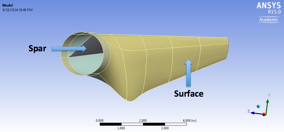
The blade is composed of an outer surface and an inner spar. The thickness of the outside surface linearly decreases from 0.1 m at the root to 0.005 m at the tip. The spar has a similar thickness behavior with 0.1 m at its closest point to the root and 0.03 m at the tip. To sum up, here are the thickness specifications needed along with their location with respect to the global coordinate system (which represents the center of an imaginary hub and thus the center of rotation).
Surface
| X (m) | Thickness (m) |
|---|---|
| -1 | 0.1 |
| -44.2 | 0.005 |
Spar
| X (m) | Thickness (m) |
|---|---|
| -3 | 0.1 |
| -44.2 | 0.03 |
These thicknesses are actually very close to what you would encounter on a real turbine.
Wind turbine blades are now made of composite materials to reduce the weight of these massive machines. Here we simplify the structural analysis by assuming that the composite material can be approximated by the following orthotropic material properties.
Density |
|---|
(kg/m^3) | 1550 |
|---|---|
Young's Modulus-X (Pa) | 1.1375E+11 |
Young's Modulus-Y (Pa) | 7.583E+09 |
Young's Modulus-Z (Pa) | 7.583E+09 |
Poisson's Ratio-XY | 0.32 |
Poisson's Ratio-YZ | 0.37 |
Poisson's Ratio-XZ | 0.35 |
Shear Modulus-XY (Pa) | 5.446E+09 |
Shear Modulus-YZ (Pa) | 2.964E+09 |
Shear Modulus-XZ (Pa) | 2.964E+09 |
*Include more details on the boundary conditions?
Option #2 (almost exact copy of Edwin's text):
This steady-state 1-way FSI (Fluid-Structure Interaction analysis that uses Fluent+Mechanical) example considers the deformation due to aerodynamic loading of a wind turbine blade. The blade is 27m long with a rotational velocity of 2.43 rad/s. The upstream wind speed is 8 m/s. The Computational Fluid Dynamics (CFD) is performed using ANSYS Fluent to develop the aerodynamic loading on the blade (Part 1 of this tutorial). The pressure on the wetted areas of the blades are the passed as a pressure load in ANSYS Mechanical which performs the Computational Structural Mechanics (CSM) to determine stresses and deformations on the blade (Part 2 of this tutorial).
Material??
| Note |
|---|
Under Construction |
In Part 2
This section involves the solid mechanics aspects of this wind turbine blade tutorial. The pressures load found using Fluent in Part 1 are imported in Mechanical and the stresses and deformations on the blade are subsequently determined.
These values are representative of composite properties found in real wind turbine blades.
Let's get started!
...
Go to Step 1: Pre-Analysis & Start-Up
...