 Sign-up for free online course on ANSYS simulations!
...
- Suppress Blade FEA
- Show the fluid geometry, wireframe.
- Create named selections
- Inlet
- Inlet-Top
- Outlet
- Blade (select all then control click the surfaces not wanted)
- Periodic 1 (one of the quadrilateral surfacesurfaces).
- Periodic 2 (the other quadrilateral surface).
- Fluid
...
Global Mesh Controls
We start by applying specifying some global mesh settings which means that these settings will be applied to the whole mesh altogether.
Note: There have been changes to the Mesher since this video was recorded. Please see the notes under the video.
| HTML |
|---|
<iframe width="640" height="360" src="//www.youtube.com/embed/ShSXdbABclo" frameborder="0" allowfullscreen></iframe> |
...
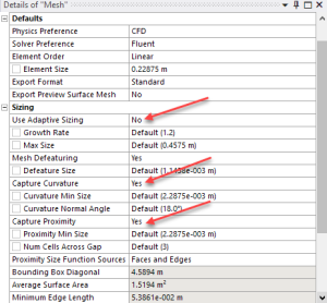
- Automatically optimized for CFD and FLUENT, tetrahedral cells.
- Change use advanced size function to proximity and curvature. It makes it deal with curves better, lower skewness.
- Change relevance center to medium.
| Note | ||
|---|---|---|
| ||
Skip the relevance center settings shown in this video. Your "Details of Mesh" window should look like the image below:
|
...
Local Mesh Controls
After applying controls to the whole mesh, we now apply mesh settings to specific areas of our geometry.
...
- Insert Match Control
- Select the two trapezoid faces for the high and low geometry selection
- Choose axis of rotation to be global coordinate
- Match control is for the nodes to match up for the periodic sides.
- Insert face sizing
- Use the name selection, blade surface.
- Input sizing of 0.3m.
- Behavior should be hard.
- Insert local inflation around the blade
- Geometry is the whole body
- For boundary, select named selection and choose the blade (click enter)
- Keep default settings for the rest
- Add a sphere of influence
- First, create a new coordinate system.
- Define it by named selections and choose the blade surface.
- Insert body sizing
- Geometry, the whole body
- Type: sphere of influence
- Sphere center: Coordinate System
- Radius: 30m
- Element size: 2m
- First, create a new coordinate system.
- Click Generate
| Note | ||
|---|---|---|
| ||
If your mesh fails when you insert a sphere of influence, skip this step. Instead, change the growth rate to 1.15 from the default of 1.2. To do this, highlight Mesh in the tree, then look under Sizing. |
...
Mesh Metrics
We now show you how to judge the quality of your mesh. This is an extremely important step because a bad mesh can lead to bad results!
...
- Skewness and orthogonal quality are the two most important. Skewness better for CFD.
- Look at the skewness mesh metric under details of mesh.
- Click on different ranges to see the specific cells in that range
| Note | ||
|---|---|---|
| ||
In newer versions, the Mesh Metrics can be viewed under Quality instead of under Statistics:
|
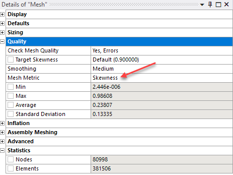
It is generally advised to keep the minimum orthogonality greater than 0.15 and maximum skewness lower than 0.95. Having bad cells or elements can lead to incorrect simulation results. However, these are general guide rules and depend on the physics solved or where the cells are located. The following tables can help you gauge the quality of your mesh.
...