 Sign-up for free online course on ANSYS simulations!
...
Let's create a line corresponding to the undeformed neutral axis. Click once on the Sketching tab,  , which appears at the bottom of the Tree Outline. Click once on the Line button,
  , in the Draw tab,
  , that automatically appears. Then place the mouse cursor directly over the origin of the XY plane until a P appears (the P indicates that the cursor is co-incident with the Point at the origin).

Once the P appears then click once on the mouse. Next, move the mouse over to the right so it lies somewhere on the positive x axis; Prior, to clicking again make sure that a C appears (the C indicates that the cursor is Co-incident with the horizontal axis)..

You should now have a line that starts at the origin and terminates somewhere on the positive axis.
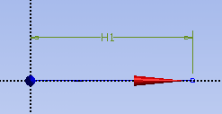
At this point, the dimension of the line needs to be specified, so click once on the Dimensions tab,  . Click on the line and place the dimension as shown below. You should see a dimension labeled H1 above the horizontal line as shown below. Note that there is an Undo button in the sketching mode that you can use if you make a mistake.
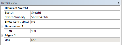
Now, the length of the line will be manually edited. Underneath the Sketching Toolboxes there will be a column called Details View. In Details View there is a subcategory called Dimensions: 1. Change the numerical value of H1 to 4 meters and press enter.
...
| Info | ||
|---|---|---|
| ||
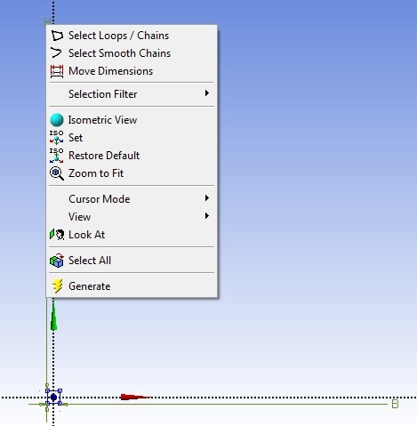
This is an optional step that will only change the way the cross-section is displayed, so you can choose to skip it. You can right click on the dimension and select Move Dimensions and move the dimensions closer to the cross section. The cross section will be easier to see if you click on the zoom to fit tool |

Assign the Cross Section
...
to the Line Body
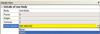
Now the defined cross section will be assigned to the line body. ANSYS will then use this cross-section to calculate the moment of inertia while forming the element stiffness matrices. First, expand "1 Part, 1 Body" which is located in the Tree Outline. Next, click on Line Body, and there should be a yellow box to the right of Cross Section under the Details of Line Body. Click on the yellow box and select rect1 as seen below.
Verify Geometry
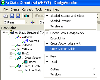
At this point the specified geometry can be checked in order to make sure all has gone well; We can visualize the beam in 3D by getting ANSYS to wrap the cross-section around the line in the display. Click on View > Cross Section Solids, as shown below;
If you click on the 1 Cross Section,  , in the Tree Outline and then click on the light blue dot,
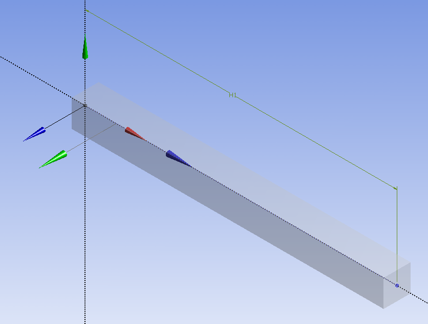
  , you should now see a three dimensionally rendered beam in an isometric view. Note that this is only a visualization; our beam model is only a line.
At this point, the Design Modeler window can be closed. Don't worry - your work will be savedThen, click on Save.