 Sign-up for free online course on ANSYS simulations!
...
First instinct is to make a rectangular solid as a model for our cantilever; While this would work, it would make the mesh more complex than it needs to be. This is a one-dimensional problem, so all we really need at our base is a one-dimensional figure: a line; (We still need to tell ANSYS it has volume, though.). This would create 3D elements which would be one way of modeling the beam. Here we will use a different modeling approach using 1D beam elements. In effect, we are only modeling the neutral axis of the beam and calculating its deformation directly. All other results such as bending stress and bending moment are derived from the deformation of the neutral axis.
Let's create a line corresponding to the undeformed neutral axis. Click once on the Sketching tab,  , which appears at the bottom of the Tree Outline. Click once on the Line button,
  , in the Draw tab,
  , that automatically appears. Then place the mouse cursor directly over the origin of the XY plane unit until a P appears (the P indicates that the cursor is co-incident with the Point at the origin).

Once the P appears then click once on the mouse. Next, move the mouse over to the right so it lies somewhere on the positive x axis; Prior, to clicking again make sure that a C appears (the C indicates that the cursor is Co-incident with the horizontal axis)..

You should now have a line that starts at the origin and terminates somewhere on the positive axis.
At this point, the dimension of the line needs to be specified, so click once on the Dimensions tab,  . Then, click once on the Horizontal button,
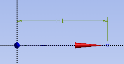
  . The next step is to click somewhere on the y axis and then click on the endpoint of the line (the point that lies upon the positive x axis). Now, raise the cursor (which should now be a horizontal line and a pencil) above the line and click once; Click on the line and place the dimension as shown below. You should see a dimension labeled H1 above the horizontal line as shown below. Note that there is an Undo button in the sketching mode that you can use if you make a mistake.
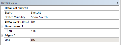
Now, the length of the line will be manually edited. Underneath the Sketching Toolboxes there will be a column called Details View. In Details View there is a subcategory called Dimensions: 1. Change the numerical value of H1 to 4 meters and press enter.
Line Body
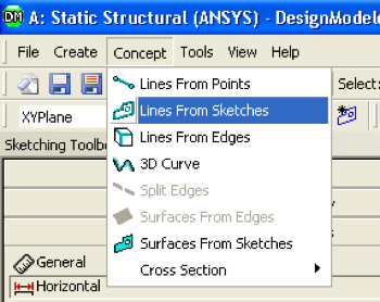
The next step is to turn the line that was drawn our "line sketch" into a "line body". In ANSYS, only "bodies" can be meshed. In order to do this click on Concept which will be on top of the Design Modeler window, then click on Lines from Sketches, as can be seen in the following picture.
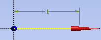
Next, click on the blue horizontal line that you drew. The blue horizontal line should have changed from blue to yellow as can be seen below.
In the Details View column a yellow box to the right of Base Objects should be highlighted in yellow. Click on the yellow box and then click apply. Then, click on the Generate button  ; it is located on the top left portion of the Design Modeler.
Cross Section
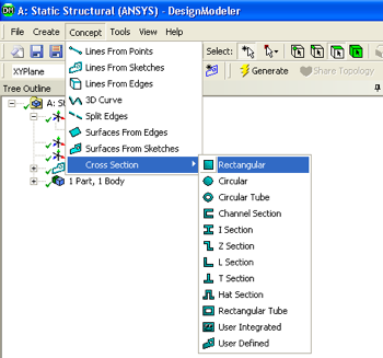
Now, a the beam cross section will be given to the line body; defined. First go to Concept then click on Cross Section then finally click on Rectangular, as shown below.
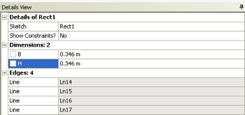
Now, the width and height of the cross section need to be defined; Under "Details View" set B to 0.346 meters and set H to 0.346 meters, as can be seen below;
Then click on the Generate button, .
| Info | ||
|---|---|---|
| ||
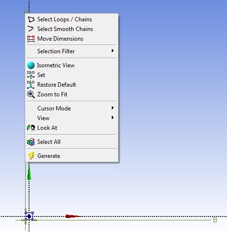
This is an optional step that will only change the way the cross-section is displayed, so you can choose to skip it. You can right click on the dimension and select Move Dimensions and move the dimensions closer to the cross section. The cross section will be easier to see if you click on the zoom to fit tool |

...
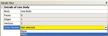
Now the defined cross section will be "merged" with assigned to the line body; . ANSYS will then use this cross-section to calculate the moment of inertia while forming the element stiffness matrices. First, expand "1 Part, 1 Body" which is located in the Tree Outline. Next, click on Line Body, and there should be a yellow box to the right of Cross Section under the Details of Line Body. Click on the yellow box and select rect1 as seen below. ANSYS will calculate the moment of inertia along the line body rather than the rectangular model.
Verify Geometry
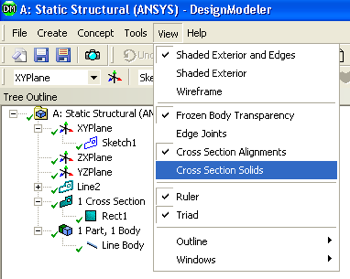
At this point the specified geometry can be checked in order to make sure all has gone well; Click on View > Cross Section Solids, as shown below;
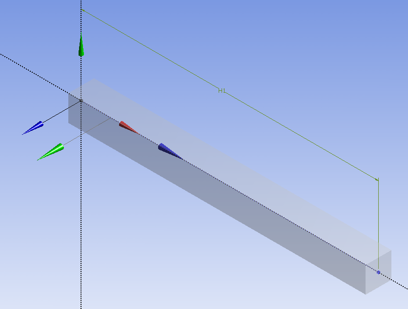
If you click on the 1 Cross Section,  , in the Tree Outline and then click on the light blue dot,
  , you should now see a three dimensionally rendered beam in an isometric view;
At this point, the Design Modeler window can be closed. Don't worry - your work will be saved.
...