 Sign-up for free online course on ANSYS simulations!
| Include Page | ||||
|---|---|---|---|---|
|
| Include Page | ||||
|---|---|---|---|---|
|
Mesh
Mapped Face Meshing
First, we will apply a mapped face meshing control to the geometry. In the Outline window, click on Mesh to bring up the Meshing Toolbar. In the Meshing Toolbar, select Mesh Control > Mapped Face Meshing. Making sure the face selection filter is selected  , select all four faces by holding down the right mouse button and dragging the mouse of all of the quadrants of the geometry. When all of the faces are highlighted green, in the Details view Window select Geometry > Apply. Next, select
Edge Sizing
Next, we will apply edge sizing controls to all of the edges of the mesh. To begin, go to Mesh Control > Sizing. Next, click the edge selection filter  . Select the following 4 edges buy holding Ctrl and using the left mouse button:
...
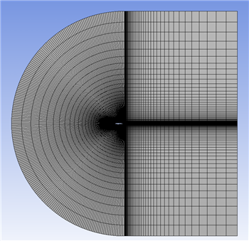
Now, select Mesh > Generate to generate the mesh. It should look like this.
Named Selections
Now will assign names to some of the edges to make creating boundary conditions for the mesh easier. Let's recall the boundary conditions we planned in the Pre-Analysis Step:
...
The edges highlighted blue are the inlet, the edges highlighted red are the outlet, and the airfoil is highlighted white in the middle. Now we are ready to name the sections. In the Outline window, select geometry - this will make seeing the edges a little easier. Again make sure the edge selection tool is selected. Now, select the two vertical edges on the far right side of the mesh. Right click, and select Create Named Selections. Name the edges outlet. Next, select the edges that correspond to the inlet of the flow as defined by the picture above. Again, right click and select Create Named Selections and this time name the selection inlet. Finally, select the two edges making up the airfoil, and name the selection airfoil.
Go to Step 4 - : Physics Setup (Physics)
Go to all FLUENT Learning Modules
See and rate the complete Learning Module