 Sign-up for free online course on ANSYS simulations!
| Include Page | ||||
|---|---|---|---|---|
|
...
| Include Page |
|---|
...
Author: Ben Mullen, Cornell University
Problem Specification
1. Pre-Analysis & Start-Up
2. Geometry
3. Mesh
4. Setup (Physics)
5. Solution
6. Results
7. Verification & Validation
|
Mesh
Initial Setup
Close the Design Modeler if you haven't already, and open ANSYS Mechanical by double clicking  When ANSYS Mechanical opens, notice that there is a question mark next to Geometry in the Project Outline - this means that there is something missing in this section. Expand Geometry, expand Part 3, and select any of the surface bodies.
...
There should no longer be a question mark next to Geometry.
Mapped Face Meshing
Right click on Mesh and insert Mapped Face Meshing onto the top surface of the wind blade in isometric view. This will ask the meshing code to create hexahedral elements. ANSYS Mesher may create tetrahedral elements if Mapped Face Meshing is not used. In general, hex elements are more efficient that tetrahedral elements because it requires a smaller number of hex elements to mesh a model.
...
| Info | ||
|---|---|---|
| ||
Make sure you do not impose Mapped Face Meshing on the spar. |
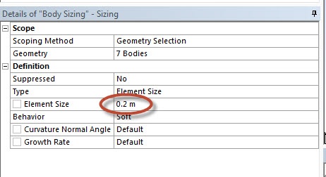
Body Sizing
Right click on Mesh and insert Sizing.
...
Change the Element Size to 0.2 m.
Generate the Mesh
Right click on Mesh and click on Generate Mesh.
...
Now that the geometry has been meshed, we are ready to setup the physics controlling the simulation.
Go to Step 4 - Setup (Physics)
See the complete Learning Module: Physics Setup