 Sign-up for free online course on ANSYS simulations!
| HTML |
|---|
<div style="background-color: yellow; border: 2px solid red; margin: 4px; padding: 2px; font-weight: bold; text-align: center;">
    This page has been moved to <a href="https://courses.ansys.com/index.php/courses/wind-blade-analysis-for-wind-power-using-ansys-fluent/lessons/pre-analysis-start-up-lesson-2-24/">https://courses.ansys.com/index.php/courses/wind-blade-analysis-for-wind-power-using-ansys-fluent/lessons/pre-analysis-start-up-lesson-2-24/</a> <br>
    Click in the link above if you are not automatically redirected in 10 seconds.
</div>
<meta http-equiv="refresh" content="10; URL='https://courses.ansys.com/index.php/courses/wind-blade-analysis-for-wind-power-using-ansys-fluent/lessons/pre-analysis-start-up-lesson-2-24/'" />
|
| Include Page | ||||
|---|---|---|---|---|
|
Pre-Analysis & Start-Up
Pre-Analysis
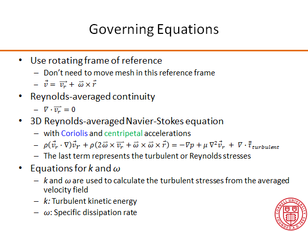
The governing equations to be solved using Ansys Fluent are shown below.
...
Pre-Analysis & Start-Up
Pre-Analysis
You are told that experiments have been performed that confirm that the tip deflection under the load is approximately
Generally, in long, slender beams, the transverse displacement due to pure bending dominates when compared with the accompanying shear deflection. In relatively short beams, however, displacement contributions from shear can be large enough as to be non-negligible compared with those from pure bending. In the present case, the shear contribution is no longer a "small percentage" of that from bending:
where the relevant shear area is approximately the area of the beam web only. This is as prescribed in most Mechanics of Materials textbooks because any load applied to the flanges tend to deform the flanges locally and do not contribute to the deflection of the neutral axis. You can see this if you attempt to perform this analysis and distribute the end load over the entire cross sectional area including the flanges.
Assuming shear modulus (G) = 3770 ksi:
Bending deformation= 0.0041033 in
Shear deformation = 0.0030557 in
Here the bending deformation alone varies enough from the total deformation to question whether the difference might be a discretization error when , in fact, it is due to a difference in physical modeling assumptions. To perform a proper validation of any numerical results post-mortem, one must know what theory is embedded within the finite element model.
When the beam is long and slender, transverse displacement due to bending is the dominant contribution to the tip deflection and the pure bending stress component is the dominant normal stress component acting at the wall fixture:
What to Expect
Performing the three-dimensional analysis results in tip deflections in agreement with theory including the shear deformation but does not render normal stresses at the wall given by simple beam theory. Below are the hand calculations for comparison in the Verification and Validation section of the tutorial:
| View file | ||||
|---|---|---|---|---|
|
Start-Up
Go to all (ANSYS or FLUENT ) Learning Modules