 Sign-up for free online course on ANSYS simulations!
Assigning Airfoils to Blade Sections
Wind turbine blades typically deflect during operation and this results in reduction in generated electrical power. We will use a steady wind field to examine the effect of blade deflection on generated electrical power.
Start-up
Double click on the Bladed icon to launch GH Bladed.
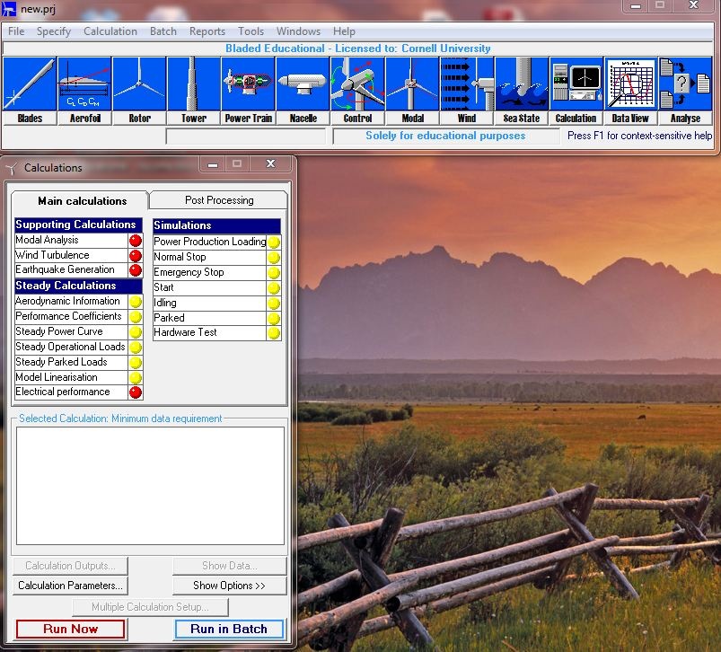
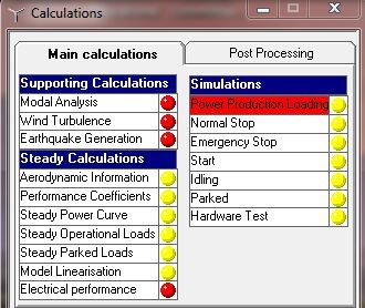
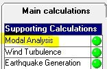
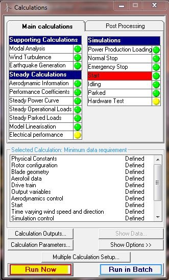
The red circles next to each calculation and simulation in the calculation window indicate none of the required input parameters are defined. The yellow circle indicates that only a part of the required inputs are defined for a given simulation. Green circle indicates all the inputs are fully defined and the simulation is ready to be carried out.
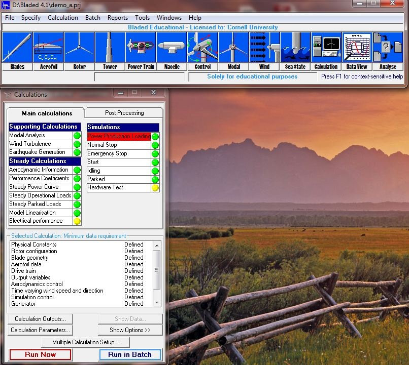
We will fist load a demo project and then adjust the desired parameters. The demo project should be in the Bladed directory. This demo project simulates a 2MW wind turbine.
File > Open Project > demo_a.prj
| Info | ||
|---|---|---|
| ||
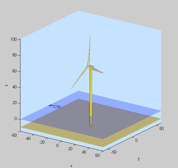
One interesting and convenient feature in GH Bladed is the built-in MATLAB model that allows the users to see the wind turbine. This feature is available when all the required physical parameters (blade and tower geometry, nacelle, etc) are fully defined. Since the demo wind turbine is fully defined, we will use this feature to visualize it. Click on the rotor icon, |

Wind
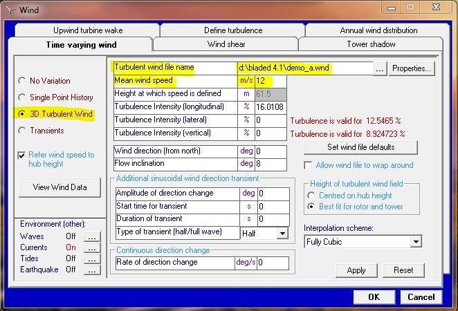
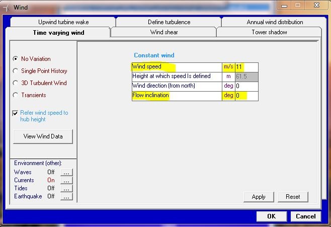
The demo project uses a pre-defined turbulence wind file. We will change the wind characteristic to steady. Click on  to edit the wind characteristic. The default wind is set to 3D Turbulent Wind with a mean wind speed of 12 m/s. This turbulent wind is defined in the demo wind file. For our case, we will use a steady wind of 11 m/s. Change the option to No Variation and change the Wind speed to 11 m/s. Change the Flow inclination to 0 degrees. Click on Apply to save the changes.
Blade Modes
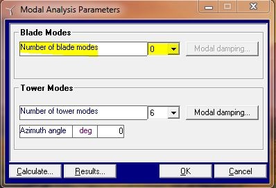
GH Bladed performs modal analysis based on the defined blade stiffness. The modes are used to predict blade deflection. Thus, we can eliminate the blade modes to simulate zero blade deflection. Double click on Modal Analysis.
Change the number of blade modes to 0. Click OK to close the Modal Analysis Parameters window.
Simulation
We will run Start simulation because it simulates the start up response of a wind turbine. Highlight Start, and click on Run Now.
A warning message will appear. This message appears because we have changed the blade modes. Click on Yes to update the modal analysis to proceed.
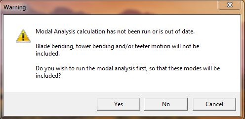
Save the simulation result in the Bladed result folder (bladed 4.1\results). Name it startup_no_blade_deflection. Close the Calculation Progress window when the run is completed.
Results
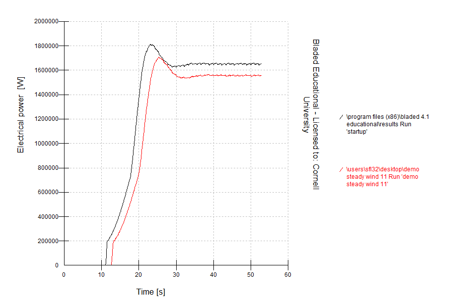
We would like to compare the electrical power output of the demo wind turbine with and without blade deflection. The result for the case with blade deflection (blade mode unchanged) is provided below. It is recommended to download and extract the results folder on the desktop (we will later browse to this folder from within Bladed).
download the result for deflected blade simulation here
Click on Data View, this is where plots are generated.

In the Graph Parameters window, click on Channel 1 to select data.
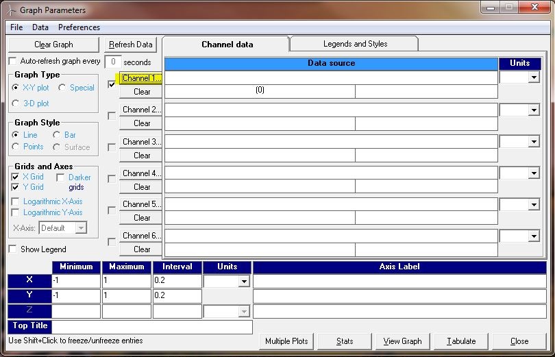
Select "startup_no_blade_deflection" under Run Name. Select Summary information in Data Group. Select Electrical power for Variables. The electrical power will be plotted against time. Click on OK to finish data selection.
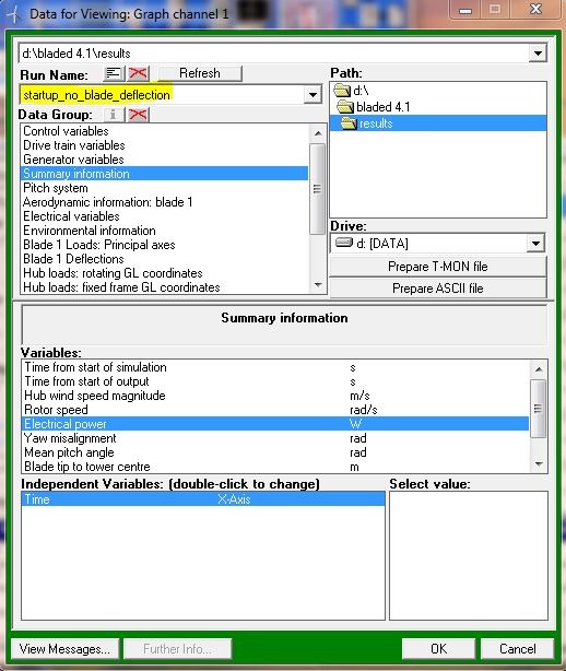
Click on Channel 2 and change the path to the desktop to find "demo_steady_wind_11". Make sure "demo_steady_wind_11" appears under Run Name. Select summary information and electrical power, as shown in the previous step.
Channel 1 displays the electrical power produced by the demo turbine without blade deflection. Channel 2 displays the electrical power produced by the demo turbine with blade deflection. Click on View Graph, and you should get something like this:
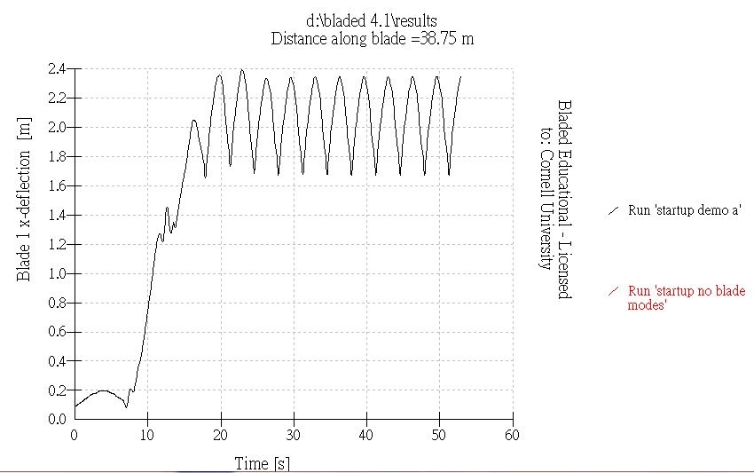
We can check if the blades in our setup deflect or not for "demo_steady_wind_11" . Select Blade 1 Deflections in Data Group. Select Blade 1 x-deflection for Variables. Select Time for Independent Variables.
Discussion
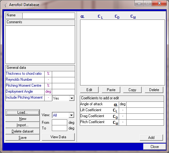
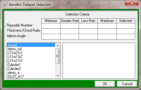
Click 'Load' in the aerofoil screen below:
This shows all of the aerofoils available:
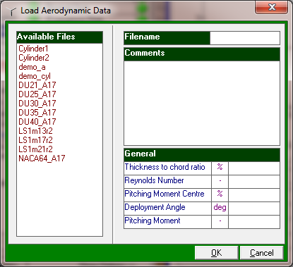
That's a total of 13 aerofoil sections available (although 3 of these appear to be just cylinders). The simplest way to use them is to go to 'define' at any blade station that you wish to change:
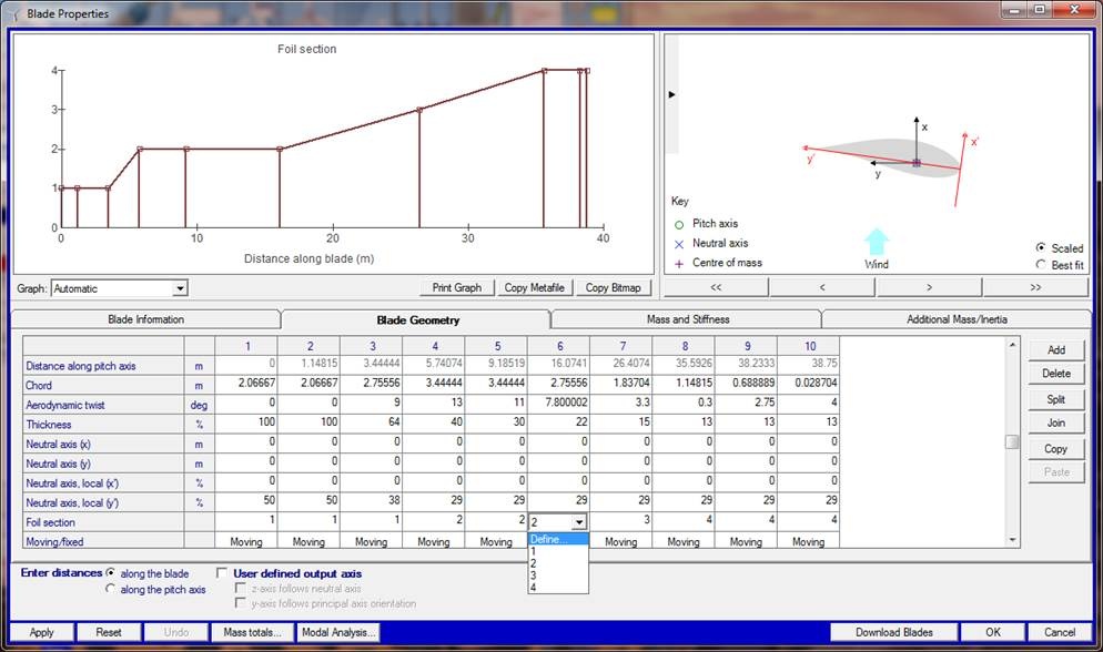

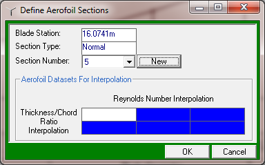
Double click in the blank white rectangle:

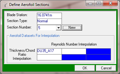
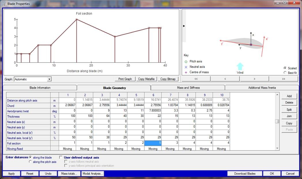
You can see that that blade station has now been changed to the newly defined blade section number 5The results agree with our expectations. Blade deflection does in fact reduces generated electrical power.