 Sign-up for free online course on ANSYS simulations!
| Include Page | ||||
|---|---|---|---|---|
|
| Include Page | ||||
|---|---|---|---|---|
|
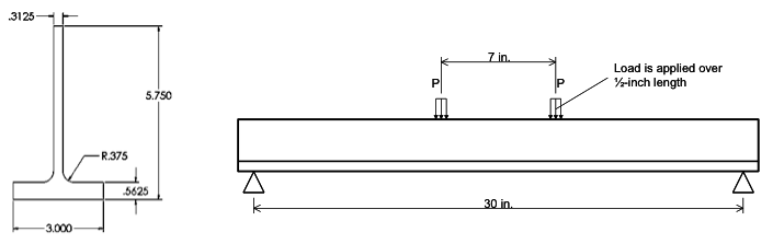
A Four-Point Bend Test on a T-Beam
Created using ANSYS 14.0
Problem Specification
This problem is taken from:
- Prantil, V. C., Papadopoulos, C. and Gessler, P. D., Lying by Approximation: The Truth About Finite Element Analysis, Morgan and Claypool (2013).
Consider a stepped shaft under an applied axial load, P. A stress concentration is apparent at the step where the cross-sectional area is discontinuous. The cross section is circular.
Learning Goals
T-beam loaded 7in apart as shown in the following figure.
Use ANSYS to display the axial stress distribution of the beam.
Learning Goals
The purpose of this tutorial is to showcase how the manner in which boundary conditions are applied will vary as the number of dimensions in the analysis increases. Further, there is no longer a single, unique prescription of the appropriate boundary condition(s). For instance, as here, a “simple support” is, in fact, not so simple in the model. The precise prescription of the boundary condition can have significant effects on the predicted stresses even in the fairly benign circumstances encountered in a four-point bend test.
Go to Step 1: Pre-Analysis & Continue to Step 1 - Pre-Analysis and Start-Up