 Sign-up for free online course on ANSYS simulations!
...
The following video shows how to add a surface to the crank model to find the average strain over the area covered by a strain gauge mounted on the crank. The video includes audio as do other videos on this page. ( Note that you have to make the following modifications to the procedure shown in the video:
- Using "Automatic Connections" to connect the crank arm and the gage doesn't always work. An alternate procedure to manually connect the two entities is shown in a later video below.
...
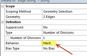
- When specifying the edge sizing for the gage, set behavior=hard" as in the snapshot below. Otherwise, ANSYS might over-ride your edge setting.
Widget Connector width 600 url http://www.youtube.com/watch?v=94o6t-LCzl4 height 370
An overview of the procedure followed in the video and explanation of the associated steps can be found in this powerpoint presentation from MAE 3272, Spring 2013.
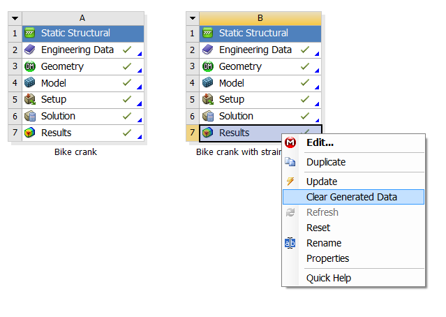
Our ANSYS Mechanical 14.0 model with a strain gage mounted can be downloaded here for your review. Download the .wbpz file and double-click on it to load it in ANSYS Workbench. To save the file in the usual .wbpj format, select File > Save as. To reduce the file size, the results have not been saved. You'll have to clear all results by selecting (right-click)Results > Clear Generated Data in the project page. Then, re-solve in ANSYS Mechanical (the red M in the taskbar) to see the results.
Manually Connecting Crank Arm and Gage
The above video shows how to add a connection between the crank arm and the gage using Create Automatic Connections. But this automated procedure doesn't always work. In that case, one has to connect the two entities manually using Insert > Manual Contact Region as shown in the video below.
...