Sign-up for free online course on ANSYS simulations!
...
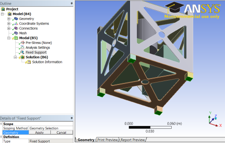
With the Design Modeler still open, right click Modal in the Outline window, then select Insert>Fixed Support. While holding down Ctrl, select the bottom face of all four -y-direction side legs.
2. Top of P-POD Constraint
The P-POD is a spring-loaded deployment system, which can hold up to three 1U CubeSats. This spring-loaded design allows for a very small amount of vertical movement during launch, while the side rails keep the CubeSat rigidly fixed in two directions. Because of the this, the side of the CubeSat facing the the sky should be constrained in all directions other than the vertical direction (+y-direction for our model). This will allow the structure to warp slightly during takeoff, and will simulate the rigid sides of the P-POD.
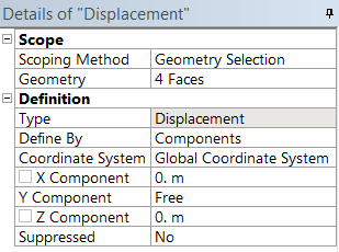
With the Design Modeler still open, right click Modal in the Outline window, then select Insert>Displacement. While holding down Ctrl, select the top face of all four +y-side legs. 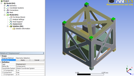
To simulate the constraint of the side rails, set the X and Y components to Constant (0 m) and the Y component to Free.