Sign-up for free online course on ANSYS simulations!
| Include Page |
|---|
...
|
...
|
| Panel |
|---|
Problem Specification |
Geometry
| Include Page | ||||
|---|---|---|---|---|
|
Geometry
| Note |
|---|
For users of ANSYS 15.0, please check this link for procedures for turning on the Auto Constraint feature before creating sketches in DesignModeler. |
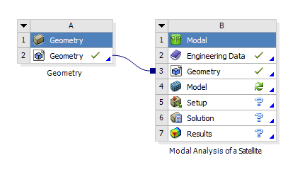
For this problem, we are going to import the geometry into ANSYS, which was designed using CAD software.
...
We can now survey the imported geometry by double clicking 
Internal Components
The internal components of this satellite have been simplified to reduce modal analysis run time. While this CubeSat structure is simple, larger satellites often have a more complex interior with a wide array of components and structural stiffeners. Features such as small extrusions, fillets not in contact with the frame and holes may be omitted to reduce the computational load of the simulation.
...
For the purposes of this tutorial, the densities for the components are provided (make sure the correct unit kg/m^3 is selected):
Large Box Density = 1000 kg/m^3
Small Box Density = 900 kg/m^3
Cylinder Density = 1200 kg/m^3
1. Assigning Material to a Component
Now we can assign the new material densities to the internal components. Left click Return to Project > Model to return to the Design Modeler. Now open up the Geometry drop down list and select "Large Box 1" and "Large Box 2". Right click Material > Assignment > Large Box.
...
Now assign the small box material to "Small Box 1" and the cylinder material to "Cylinder". The internal components will now simulate a more realistic mass rather than a solid piece of aluminum.
2. Geometry Connections
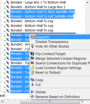
To simplify the model, we assume that most of the structure is rigid and bonded together. However, for our model we will assume that none of the satellite walls are bonded to each other, instead they are bolted to the four supports. Modeling these connections can be achieved in a few steps.
...
Because the walls are not physically bonded to each other, we must suppress every wall-to-wall connection. While holding the Ctrl key, select every wall-to-wall connection. There should be 12 wall-to-wall connections. Right click the selection > Supress.