 Sign-up for free online course on ANSYS simulations!
...
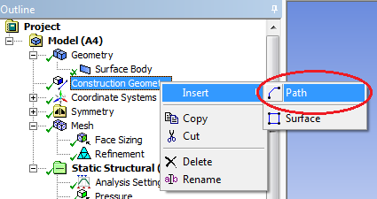
Right click on construction geometry and insert a path :and rename it "left edge".
Enter the following start and end coordinates:
...
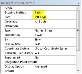
You should see a gray path displayed on the left edge of the model. Create another normal stress, as you did in the previous step. Change the scoping method to Path and select left edge for Path.
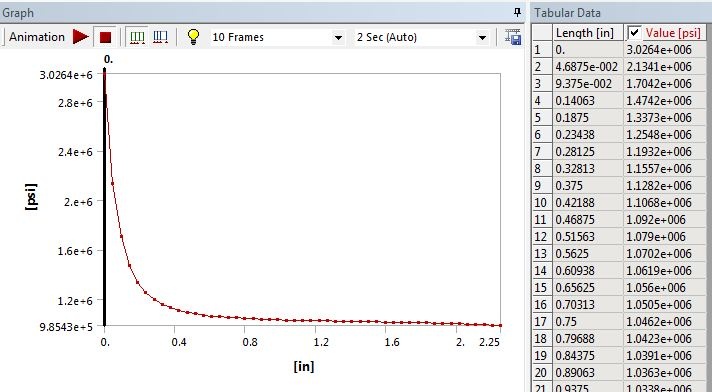
Click on Solve to generate the result. ANSYS Mechanical will plot the stress along the left edge and the data is tabulated.
Continue to Step 7 - Verification and Validation
Go to all ANSYS Learning Modules
See the complete Learning Module