 Sign-up for free online course on ANSYS simulations!
...
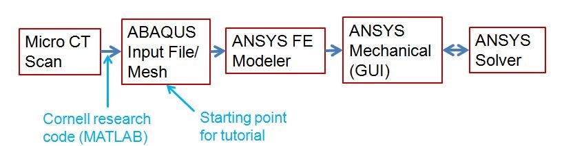
The following flow chart illustrates the steps to carry out ANSYS simulation starting from Micro CT Scan.
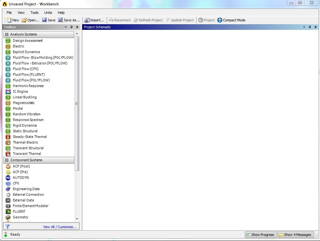
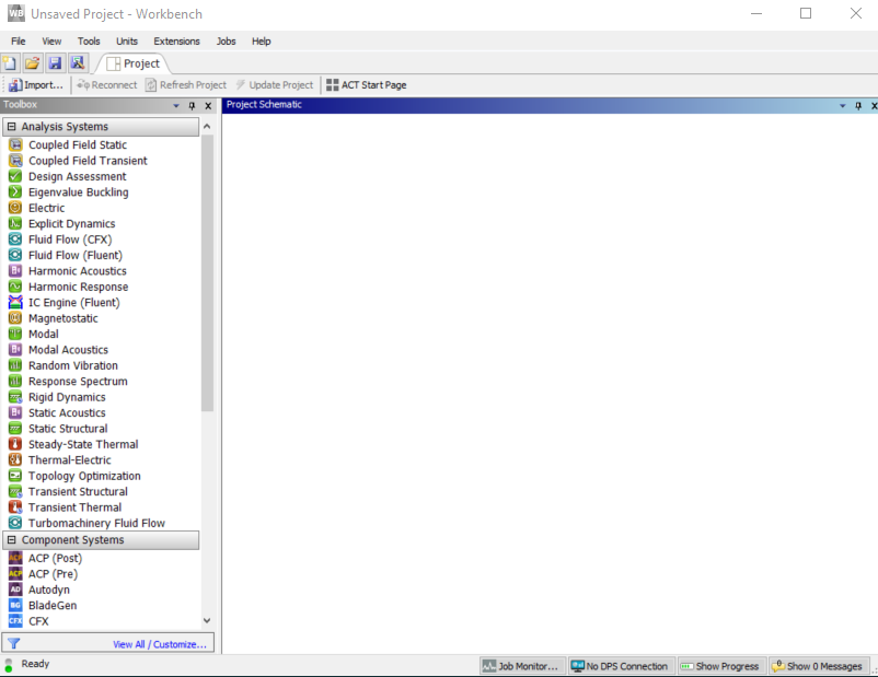
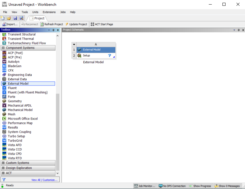
Open ANSYS Workbench:
We will import the Abaqus input file into Finite Element Modeler External Model and convert it into a model Geometry Setup that ANSYS can simulate.
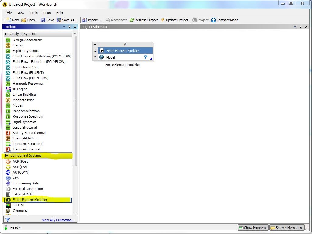
Expand Component Systems in the Toolbox. Locate Finite ElementModeler External Model and drag it into Project Schematic:
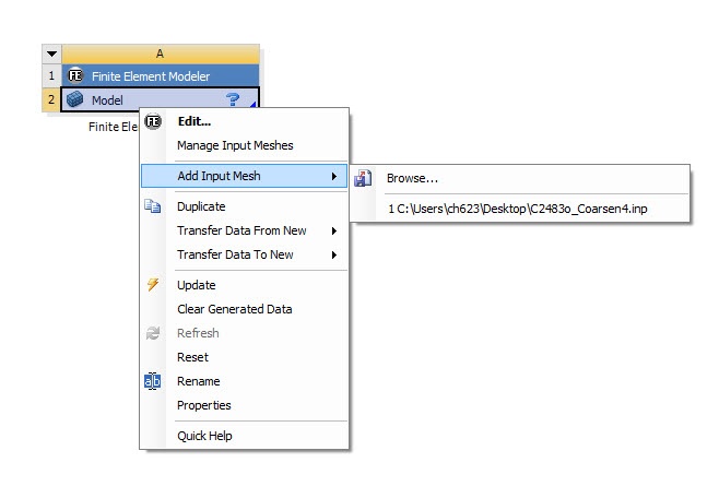
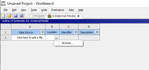
Right click on Model > Add Input Mesh Setup > Edit > Location >Browse, and locate the Abaqus input file.
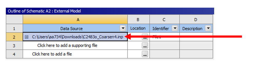
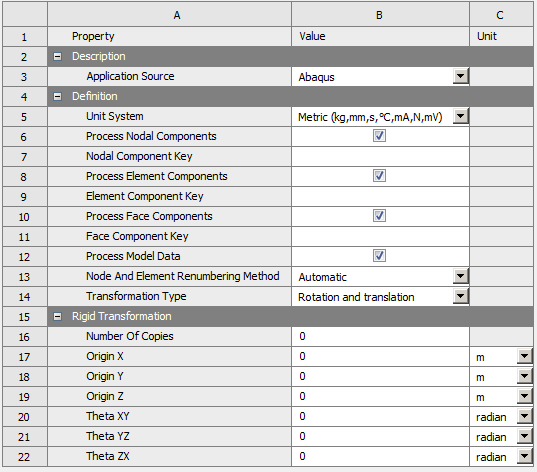
Once the Abaqus file is imported, make sure that the Unit System selected are in mm. Click on the Data Source cell (Cell A2), then check the unit system is as shown below:
Click on the Project Tab to return to Project Schematic. You should see an update symbol 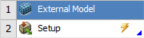 next to SetupYou should see a refresh symbol
  next to Model. This means the input file has been loaded and FE modeler External Model is ready to generate a geometry. Double click on Model to launch the FE Modelermodel.