 Sign-up for free online course on ANSYS simulations!
| Include Page |
|---|
...
|
...
|
| Include Page |
|---|
...
|
...
|
| Note |
|---|
Note to Cornell students in MAE 3250, Fall 2015: You only need to complete Exercise 2. |
Exercise 1
A steel bar with E=200GPa and a Poisson's ratio of 0.3 is loaded as shown with a distributed load totaling 50,000 N applied to the right end. The bar is 10 mm thick, and other dimensions are give in millimeters.
...
c. Discuss how the maximum stress and maximum displacement change when the radius is reduced.
Exercise 2
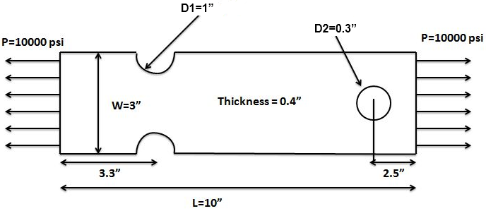
Consider the bar shown below. It is 10 inches long, 3 inches wide (w), and 0.4 inches thick. The groove radius r is 0.5 inches, and the diameter d of the hole is 0.3 inches. The applied traction P is 10,000 psi. The plate is made of A514 steel with a modulus of elasticity of 29e6 psi and a Poisson of 0.3. Assume plane stress conditions are valid. Obtain the finite-element solution for this problem using ANSYS.
Assignment:
1. Make a plot of the mesh.
2. Make a plot of the deformed shape. Include the undeformed shape in the same plot (see tip below on how to turn this on). Using this plot, discuss whether you have applied the displacement boundary conditions correctly.
3. Compare Compare the displacement at the right edge (relative to the left) with a back-of-the-envelope estimate.
4. Make a plot of the Sigma_xx variation in the bar. Deduce the stress concentration factor for the hole on the right from this plot. Compare this to the theoretical value for a small hole in an infinite plate.
5. Determine how your stress concentration factor changes when you use a different mesh. Indicate the number of nodes and elements for your two meshes (this info can be found in "Details of mesh" when expanding "Statistics"). Also, include a plot of your second mesh.
Tips:
...
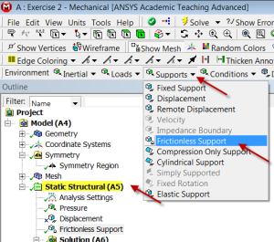
You need to constrain your ANSYS model adequately so that it doesn't fly off to Europa. The figure above doesn't specify any displacement boundary conditions. You can make use of symmetry to impose the y-displacement constraint. Additionally, set the x-displacement on left edge to be zero by selecting Supports > Frictionless Support as shown below. With these two displacement boundary conditions, the model is well constrained while also being consistent with the figure above.
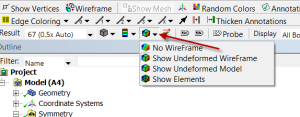
You can turn on the undeformed wireframe using the button shown below.
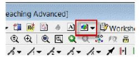
1. You can save a copy of a plot using the following icon in the top menu:
Or you can use the Snipping Tool in Windows 7.
Go to Comments2. If you apply pressures to both the right an left edges, you'll get an error saying that the model is insufficiently constrained. You need to have a displacement constraint to overcome this. So constrain the left edge in the x direction and apply the pressure on the right edge.