Sign-up for free online course on ANSYS simulations!
| Panel |
|---|
Author: Benjamin Mullen, Cornell University Problem Specification |
Separated Shock
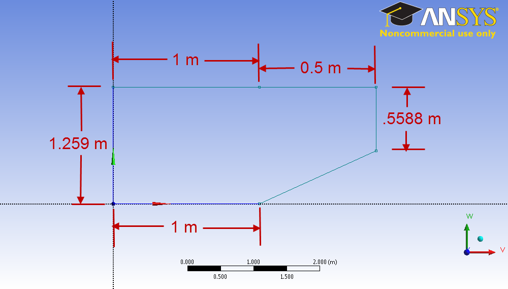
Next, we will alter the geometry to achieve a separated shock. Close FLUENT and open the Design Modeler. We want to increase the angle of the wedge above its critical angle. We will increase the angle to 35 degrees. Change the geometry's dimensions to match that of the diagram below.
Once the geometry has changed, close the design modeler. We will have to re-calculate the solution, but we will want to change some factors affecting the solution. Usually, when you make an upstream change in ANSYS, the program will update all of the downstream data. We want to break this connection, so right click  and select
Reset. We will have to input the boundary conditions again, but that shouldn't take long – and will end up saving us time when we calculate the solution inside of the FLUENT environment.
Next, open up the mesher by double clicking  . Update the mesh by clicking
  . Close the mesher, click
  , then once again double click . Re-enter all of the data from Step 5 (here is link for reference). This time, set the Courant Number to 1.0. This will make the solution a little more unstable, but it will solve much, much faster. Run the solution again, this time with 5000 iterations.

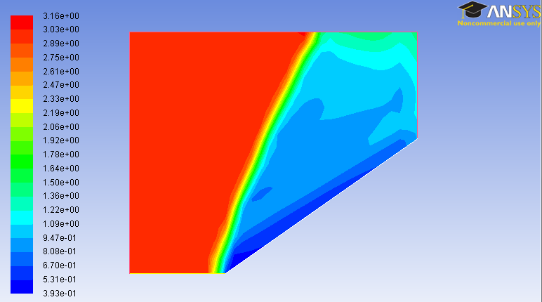
Plot the contour plot of the mach number to see how the shock has changed.