 Sign-up for free online course on ANSYS simulations!
| Include Page | ||||
|---|---|---|---|---|
|
| Include Page | ||||
|---|---|---|---|---|
|
| Include Page | ||||
|---|---|---|---|---|
|
Step 6: Results
Total Deformation
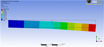
First, examine the total deformation by clicking on the Total Deformation button,  . If you have used only two elements, you should see the output shown below.
| newwindow | ||||
|---|---|---|---|---|
| ||||
| Wiki Markup | ||||
{include: ANSYS 12 - Cantilever Beam - Panel} {include: ANSYS Google Analytics}{include: ANSYS Google Analytics} h2. Step 6: Results h4. Total Deformation First, examine the total deformation by clicking on the Total Deformation button, !Totaldeform.png!. If you have used only two elements, you should see the output shown below. !2Elem_Tot_Def_Cornellian_350.png! {newwindow:Click Here for Higher Resolution}https://confluence.cornell.edu/download/attachments/125812731/2ElemTotDef_Cornellian_Full.png{newwindow} \\ \\ If you have chosen to use 10 elements for your mesh, you should see the following output for the total deformation. !10ElemDefCornellian_350.png! {newwindow:Click Here for Higher Resolution} |
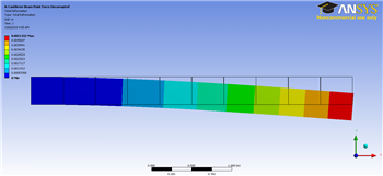
If you have chosen to use 10 elements for your mesh, you should see the following output for the total deformation.
| newwindow | ||||
|---|---|---|---|---|
| ||||
https://confluence.cornell.edu/download/attachments/125812731/10ElemTotDefCornellian_full.png{newwindow}
\\
\\
The beam deformation can be animated by clicking on the play button, !playbutton.png!, which is located underneath the beam deformation results.
\\
\\

h4. Maximum Bending Stress

For this static structural problem, the maximum bending stress is of interest. In order to examine the maximum bending stress first expand the Beam Tool folder, !BeamTool.png!, which is located under |
The beam deformation can be animated by clicking on the play button,  , which is located underneath the beam deformation results.
Maximum Bending Stress
For this static structural problem, the maximum bending stress is of interest. In order to examine the maximum bending stress first expand the Beam Tool folder,  , which is located under "Solution(A6)".
...
Next,
...
click
...
on
...
the
...
Maximum
...
Bending
...
Stress
...
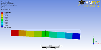
button,  . If you have used only two elements, you should obtain the following output.
| newwindow | ||||
|---|---|---|---|---|
| ||||
!maxbendstressbutton.png!. If you have used only two elements, you should obtain the following output. !2elemmaxbendavg.png! {newwindow:Click Here for Higher Resolution}https://confluence.cornell.edu/download/attachments/125812731/2elemmaxbendavg_full.png{newwindow} \\ \\ By |
By default,
...
ANSYS
...
averages
...
the
...
stress
...
values
...
over
...
the
...
length
...
of
...
the
...
beam.
...
Using
...
only
...
two
...
elements,
...
this
...
yields
...
a
...
minimum
...
value
...
of
...
2.3176e6
...
Pa
...
for
...
the
...
maximum
...
bending
...
stress.
...
This
...
is
...
an
...
error
...
created
...
by
...
the
...
small
...
number
...
of
...
elements
...
used.
...
The
...
minimum
...
value
...
of
...
bending
...
stress
...
should
...
be
...
zero
...
because
...
there
...
is
...
no
...
moment
...
where
...
the
...
force
...
is
...
applied.
...
However,
...
because
...
ANSYS
...
is
...
displaying
...
the
...
maximum
...
bending
...
stress,
...
and
...
we
...
are
...
using
...
such
...
a
...
small
...
number
...
of
...
elements,
...
it
...
will
...
not
...
display
...
the
...
zero
...
stress
...
at
...
the
...
end.
...
Next,
...
we
...
will
...
verify
...
that
...
ANSYS
...
is
...
calculating
...
the
...
correct
...
bending
...
stress
...
at
...
the
...
end.
...
by
...
displaying
...
the
...
bending
...
moment.
...
If
...
the
...
bending
...
moment
...
is
...
zero
...
at
...
the
...
application
...
of
...
force,
...
then
...
the
...
bending
...
stress
...
is
...
zero
...
as
...
well.
...
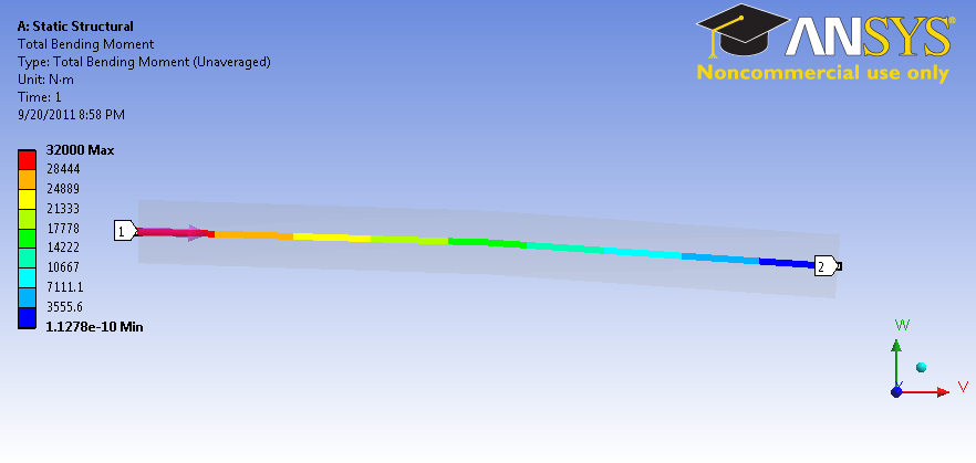
Bending
...
Moment
...
To
...
view
...
the
...
bending
...
moment
...
along
...
the
...
beam,
...
click
...
Total
...
Bending
...
Moment
...
in
...
the
...
Outline
...
window.
...
You
...
should
...
see
...
the
...
following
...
in
...
the
...
graphics
...
window.
| newwindow | ||||
|---|---|---|---|---|
| ||||
!BendingMoment.png|width=350! {newwindow:Click here to enlarge}https://confluence.cornell.edu/download/attachments/125812731/BendingMoment.png?version=1&modificationDate=1316567309000{newwindow} |
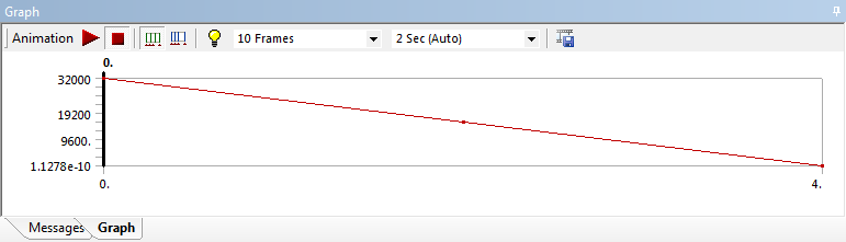
Also
...
notice
...
that
...
the
...
values
...
were
...
plotted
...
in
...
a
...
graph
...
in
...
the
...
Graph
...
window.
| newwindow | ||||
|---|---|---|---|---|
| ||||
!Graph.png|width=350! {newwindow"Click here to enlarge}https://confluence.cornell.edu/download/attachments/125812731/Graph.png?version=1&modificationDate=1316567430000{newwindow} [*Go to Step |
...
...
...