 Sign-up for free online course on ANSYS simulations!
...
| Include Page | ||||
|---|---|---|---|---|
|
Step 2: Geometry
Initial settings
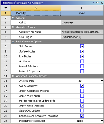
In order to make sure to get the geometry data transferred to the Model a couple of steps must be taken; First, right click on "Geometry" then click on "Properties". Under "Properties of Schematic A3: Geometry" expand "Basic Geometry Options" and check the box to the right of "Line Bodies" as seen below.
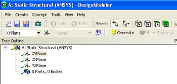
Double-click on the geometry button,  , in the Project Schematic area, which should launch the Design Modeler in ANSYS. A window should pop up asking for units. Units are in meters, so select Meters and press Ok. A folder called "A: Static Structural (ANSYS) should be expanded in the tree outline of the Design Modeler. If it is not expanded, then expand it now.
...
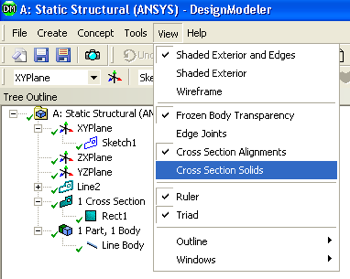
At this point the specified geometry can be checked in order to make sure all has gone well. Click on "View" and then "Cross Section Solids", as shown below.
If you click on the "1 Cross Section", 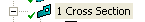 , in the Tree Outline and then click on the light blue dot,
  , you should now see a three dimensionally rendered beam in an isometric view.
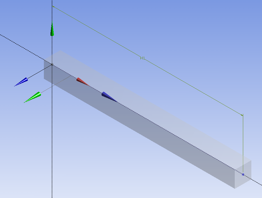
At this point, the Design Modeler window can be closed.
Exporting The Geometry to The Model
In order to make sure to get the geometry data transferred to the Model a couple of steps must be taken. First, right click on "Geometry" then click on "Properties". Under "Properties of Schematic A3: Geometry" expand "Basic Geometry Options" and check the box to the right of "Line Bodies" as seen below.
See and rate the complete Learning Module
...