 Sign-up for free online course on ANSYS simulations!
| Include Page |
|---|
...
|
...
|
| Panel |
|---|
Author: Ben Mullen, Cornell University Problem Specification |
Mesh
| Include Page | ||||
|---|---|---|---|---|
|
Mesh
| Note |
|---|
This tutorial is not being updated any more. We recommend that you follow this newer tutorial on fluid-structure analysis of a wind turbine blade. Thank you! |
Initial Setup
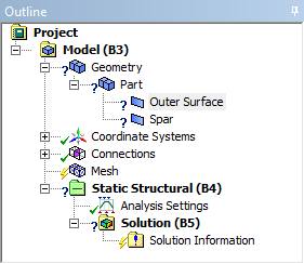
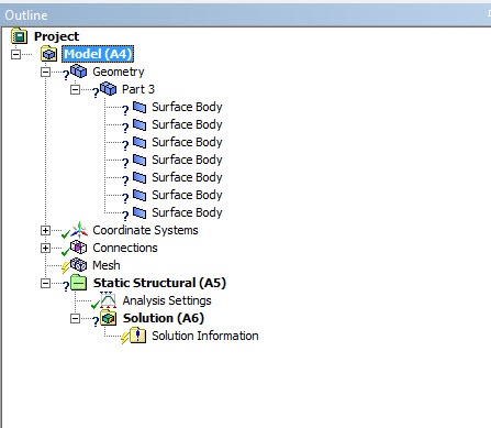
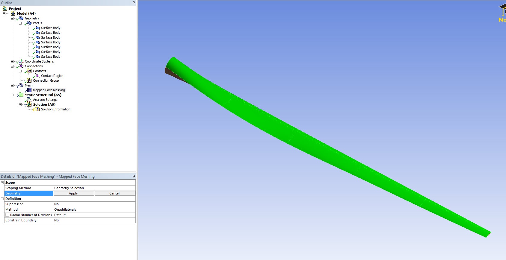
Close the Design Modeler if you haven't already, and open ANSYS Mechanical by double clicking  When ANSYS Mechanical opens, notice that there is a question mark next to Geometry in the Project Outline - this means that there is something amiss missing in this section. Expand Geometry, expand Part 3, and select any of the first surface bodybodies.
Also notice Notice that Thickness is highlighted as it does not have a value specified. Although we will ultimately specify a varying thickness for the the wind turbine blade, for now we will specify a unit thickness. We need to do this or ANSYS will fail when it tries to solve. For each dummy thickness so the geometry will mesh correctly. For this surface body, enter 1 1e-5 next to Thickness. Repeat with the same value for all other surface bodies.
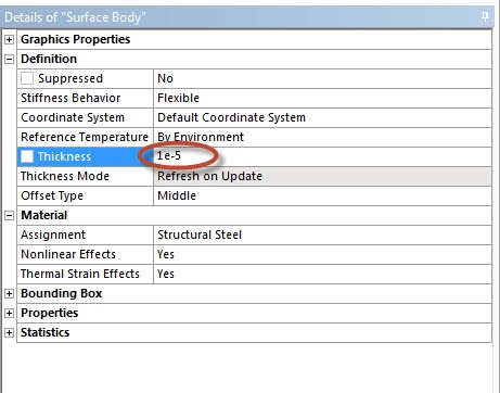
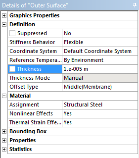
There should no longer be a question mark next to Geometry.
Body Sizing
For this geometry, we will be using a body sizing. Click on Mesh in the Project Outline window to open up the Meshing Menu in the menu bar. To create a new sizing, go to Mesh Control > Sizing. Next, we need to select the geometry that the sizing will affect. We want to select the entire geometry. To do this, first select the body sizing filter  . Next, hold down Ctrl and click on the outer surface of the wind turbine blade, as well as the spar on the inside of the blade.
We you have selected the two geometries, click Apply. Next to Geometry it should now say 2 Bodies. Specify the Element Size to 0.30. Finally, press Mesh > Generate Mesh to generate the mesh. The final result should look something like the image below.
Mapped Face Meshing
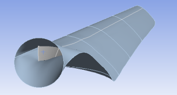
Right click on Mesh and insert Mapped Face Meshing onto the top surface of the wind blade in isometric view. This will ask the meshing code to create hexahedral elements. ANSYS Mesher may create tetrahedral elements if Mapped Face Meshing is not used. In general, hex elements are more efficient that tetrahedral elements because it requires a smaller number of hex elements to mesh a model.
Repeat the step for the bottom surface. You may use the "Extend To Limit" tool to select all the faces instead of select them individually.
| Info | ||
|---|---|---|
| ||
Make sure you do not impose Mapped Face Meshing on the spar. |
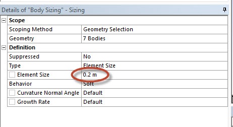
Body Sizing
Right click on Mesh and insert Sizing.
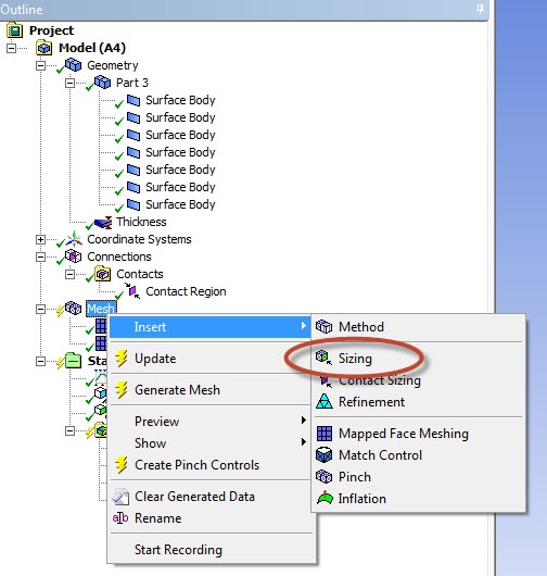
Right click in the graphics window and click on Select All.
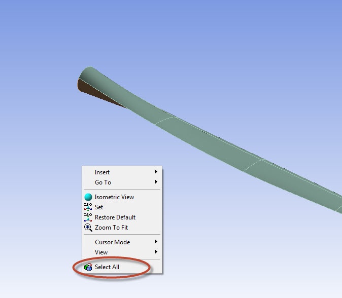
Change the Element Size to 0.2 m.
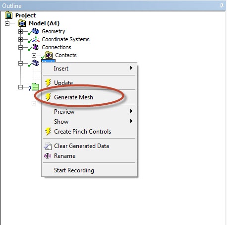
Generate the Mesh
Right click on Mesh and click on Generate Mesh.
The meshed wind blade is shown below:
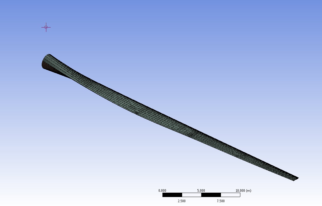
The meshed wind turbine blade consists of 7763 elements and 7566 nodes.
Now that the geometry has been meshed, we are ready to setup the physics controlling the simulation.
Go to Step 4: Physics SetupGo to Step 4 - Setup (Physics)